

General Design Principles for DuPont Engineering Polymers - Module
General Design Principles for DuPont Engineering Polymers - Module
General Design Principles for DuPont Engineering Polymers - Module

Create successful ePaper yourself
Turn your PDF publications into a flip-book with our unique Google optimized e-Paper software.
The wear per<strong>for</strong>mance of Delrin ® 500, Delrin ® 900 F<br />
and Delrin ® 500 CL are illustrated in Figure 7.02<br />
against mild steel. Comparable data have also been<br />
obtained to show the suitability of Delrin ® acetal resin<br />
with aluminum and brass. When loads and operating<br />
speeds are low, as in clocks and hand-operated window<br />
crank drives, anodized aluminium and hard brass<br />
can be used as bearing surfaces with Delrin ® acetal<br />
resin. Figure 7.03 shows wear of Zytel ® 101 running<br />
against steel without lubricant at a PV of 3000.<br />
The actual wear per<strong>for</strong>mance of specific resins will<br />
vary depending upon load, speed, mating surface,<br />
lubrification and clearance. Wear data can be found in<br />
the product modules.<br />
A bearing surface should always be provided with<br />
interruptions to allow wear debris to be picked up and,<br />
as much as possible, to be removed from the rubbing<br />
Figure 7.02 Wear of Delrin ® 500 against mild steel*<br />
Wear<br />
Delrin ®<br />
500<br />
Delrin ®<br />
900 F<br />
Time of Test<br />
Delrin ®<br />
500 CL<br />
*Thrust washer test; non-lubricated; P, 0.4 MPa (5.7 psi); V, 0.95 m/s (190 fpm)<br />
Note: Delrin ® 900 F was previously coded Delrin ® 8010.<br />
Figure 7.03 Typical wear of Zytel ® 101 against ground<br />
carbon steel<br />
No lubricant, PV = 3,000<br />
lb ft<br />
×<br />
in2 min<br />
40<br />
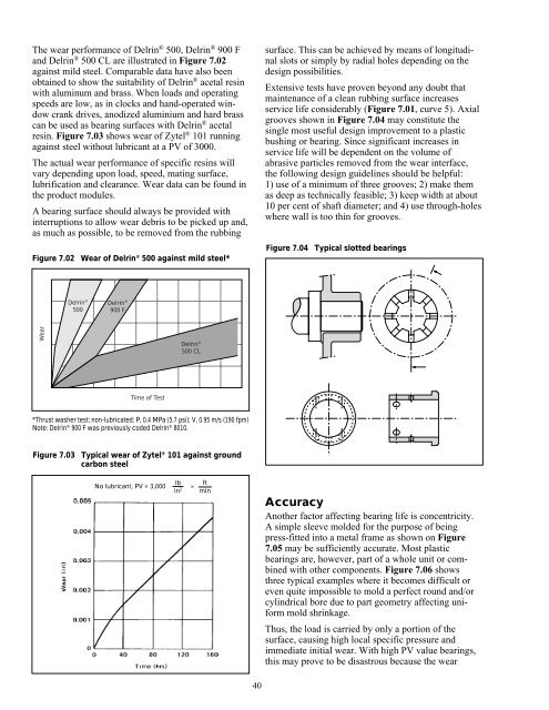
surface. This can be achieved by means of longitudinal<br />
slots or simply by radial holes depending on the<br />
design possibilities.<br />
Extensive tests have proven beyond any doubt that<br />
maintenance of a clean rubbing surface increases<br />
service life considerably (Figure 7.01, curve 5). Axial<br />
grooves shown in Figure 7.04 may constitute the<br />
single most useful design improvement to a plastic<br />
bushing or bearing. Since significant increases in<br />
service life will be dependent on the volume of<br />
abrasive particles removed from the wear interface,<br />
the following design guidelines should be helpful:<br />
1) use of a minimum of three grooves; 2) make them<br />
as deep as technically feasible; 3) keep width at about<br />
10 per cent of shaft diameter; and 4) use through-holes<br />
where wall is too thin <strong>for</strong> grooves.<br />
Figure 7.04 Typical slotted bearings<br />
Accuracy<br />
Another factor affecting bearing life is concentricity.<br />
A simple sleeve molded <strong>for</strong> the purpose of being<br />
press-fitted into a metal frame as shown on Figure<br />
7.05 may be sufficiently accurate. Most plastic<br />
bearings are, however, part of a whole unit or combined<br />
with other components. Figure 7.06 shows<br />
three typical examples where it becomes difficult or<br />
even quite impossible to mold a perfect round and/or<br />
cylindrical bore due to part geometry affecting uni<strong>for</strong>m<br />
mold shrinkage.<br />
Thus, the load is carried by only a portion of the<br />
surface, causing high local specific pressure and<br />
immediate initial wear. With high PV value bearings,<br />
this may prove to be disastrous because the wear


