

General Design Principles for DuPont Engineering Polymers - Module
General Design Principles for DuPont Engineering Polymers - Module
General Design Principles for DuPont Engineering Polymers - Module

You also want an ePaper? Increase the reach of your titles
YUMPU automatically turns print PDFs into web optimized ePapers that Google loves.
Because of the possibility of such long-term failure,<br />
designers should consider the impact grades of acetal<br />
when such criteria as stiffness, low coefficient of<br />
friction and spring-like properties indicate that acetal<br />
would be the best material <strong>for</strong> the particular application.<br />
These grades have a higher elongation, a lower<br />
mold shrinkage and better resistance to the stress<br />
concentration induced by the sharp edges of metal<br />
inserts.<br />
Since glass- and mineral-rein<strong>for</strong>ced resins offer lower<br />
mold shrinkage than their base resins, they have been<br />
used successfully in appropriate applications. Their<br />
lower elongation is offset by a typical mold shrinkage<br />
range of 0.003 to 0.010 mm/mm (in/in).<br />
Although the weld lines of heavily loaded glass or<br />
mineral-rein<strong>for</strong>ced resins may have only 60% of the<br />
strength of an unrein<strong>for</strong>ced material, the addition of a<br />
rib can substantially increase the strength of the boss<br />
(see Figure 3.27).<br />
Another aspect of insert molding that the designer<br />
should consider is the use of nonmetallic materials <strong>for</strong><br />
the insert. Woven-polyester-cloth filter material has<br />
been used as a molded-in insert in a frame of glassrein<strong>for</strong>ced<br />
nylon.<br />
Part <strong>Design</strong> <strong>for</strong> Insert Molding<br />
<strong>Design</strong>ers need to be concerned about several special<br />
considerations when designing a part that will have<br />
molded-in inserts:<br />
• Inserts should have no sharp corners. They should<br />
be round and have rounded knurling. An undercut<br />
should be provided <strong>for</strong> pullout strength (see<br />
Figure 3.28).<br />
• The insert should protrude at least 0.41 mm<br />
(0.016 in) into the mold cavity.<br />
• The thickness of the material beneath it should be<br />
equal to at least one-sixth of the diameter of the<br />
insert to minimize sink marks.<br />
• The toughened grades of the various resins should<br />
be evaluated. These grades offer higher elongation<br />
than standard grades and a greater resistance to<br />
cracking.<br />
• Inserts should be preheated be<strong>for</strong>e molding; 93°C<br />
(200°F) <strong>for</strong> acetal, 121°C (250°F) <strong>for</strong> nylon. This<br />
practice minimizes post-mold shrinkage, preexpands<br />
the insert and improves the weld-line<br />
strength.<br />
• A thorough end-use test program should be conducted<br />
to detect problems in the prototype stage of<br />
product development. Testing should include<br />
temperature cycling over the range of temperatures<br />
to which the application may be exposed.<br />
14<br />
From a cost standpoint—particularly in high-volume,<br />
fully automated applications—insert costs are comparable<br />
to other post-molding assembly operations. To<br />
achieve the optimum cost/per<strong>for</strong>mance results with<br />
insert molding, it is essential that the designer be<br />
aware of possible problems. Specifying molded inserts<br />
where they serve a necessary function, along with<br />
careful follow-up on tooling and quality control,<br />
will contribute to the success of applications where<br />
the combined properties of plastics and metals are<br />
required.<br />
Figure 3.27 Boss diameter should be two and a half<br />
times the insert diameter. Rib at weld line<br />
can increase support.<br />
t<br />
t<br />
2–2.5 D<br />
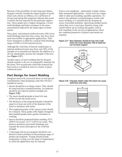
Figure 3.28 Improper depth under the insert can cause<br />
weld lines and sinks.<br />
D<br />
D<br />
t<br />
1/16 D


