

General Design Principles for DuPont Engineering Polymers - Module
General Design Principles for DuPont Engineering Polymers - Module
General Design Principles for DuPont Engineering Polymers - Module

You also want an ePaper? Increase the reach of your titles
YUMPU automatically turns print PDFs into web optimized ePapers that Google loves.
3. Vibrations, generated either by a gear box or by<br />
an electric magnet, are transmitted to the jigs and<br />
through them to the joint surfaces. The motions of<br />
the two parts take place in opposite directions,<br />
thus creating a relative velocity at the weld<br />
surfaces. As a result of friction, temperature rises<br />
immediately, reaching the melting point of the<br />
plastic, usually in less than a second.<br />
4. After a pre-set time, an electrical control device<br />
stops the vibrations whilst pressure on the joint is<br />
maintained. Simultaneously the parts are brought<br />
into the correct position relative to each other.<br />
5. Pressure is maintained <strong>for</strong> a few seconds to allow<br />
the melt to freeze. Then the jigs open and the<br />
welded parts are ejected.<br />
Basic <strong>Principles</strong><br />
The various weld methods <strong>for</strong> joining parts in thermoplastic<br />
materials differ essentially in the way heat is<br />
built up on the joint surface.<br />
The presently known procedures can be split into two<br />
basically different groups:<br />
1. The heat required to reach the melting temperature<br />
is supplied by an outside source. This is the case<br />
with hot plate welding, induction welding and hot<br />
air welding.<br />
2. The necessary heat is generated directly on the<br />
joint surfaces by means of friction. The best<br />
known methods using this procedure are<br />
spinwelding and ultrasonic welding. They have<br />
the obvious advantage that the melted resin is<br />
never exposed to open air, in this way preventing<br />
decomposition or oxidation which, <strong>for</strong> some<br />
plastics, must be avoided.<br />
Spinwelding, however, is limited to circular<br />
shaped parts which, in addition, do not require<br />
positioning. If the two items are to be joined in an<br />
exact position relative to each other spinwelding<br />
equipment becomes quite costly because there<br />
are no simple mechanical means to fulfill this<br />
requirement.<br />
Vibration welding belongs to the second group since it<br />
produces heat by means of friction on the two joint<br />
surfaces. Unlike the spinwelding procedure, vibration<br />
welding is not limited to circular parts. It can be<br />
applied to almost any shape provided that the parts are<br />
designed to permit free vibrations within a given<br />
amplitude.<br />
Definition of Motion Center<br />
The center around which two parts vibrate can be<br />
located:<br />
a) inside the joint area<br />
b) outside the joint area<br />
111<br />
c) at an infinite distance, in which case the motion<br />
becomes linear<br />
Based on this, two distinct variations can be defined:<br />
Angular and linear welding.<br />
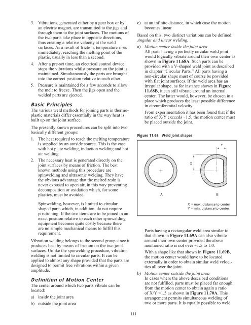
a) Motion center inside the joint area<br />
All parts having a perfectly circular weld joint<br />
would logically vibrate around their own center as<br />
shown in Figure 11.68A. Such parts can be<br />
provided with a V-shaped weld joint as described<br />
in chapter “Circular Parts.” All parts having a<br />
non-circular shape must of course be provided<br />
with flat joint surfaces. If the weld area has an<br />
irregular shape, as <strong>for</strong> instance shown in Figure<br />
11.68B, it can still vibrate around an internal<br />
center. The latter would, however, be chosen in a<br />
place which produces the least possible difference<br />
in circumferential velocity.<br />
From experimentation it has been found that if the<br />
ratio of X/Y exceeds ~1.5, the motion center must<br />
be placed outside the joint.<br />
Figure 11.68 Weld joint shapes<br />
A B<br />
X<br />
Y<br />
X = max. distance to center<br />
Y = min. distance to center<br />
Parts having a rectangular weld area similar to<br />
that shown in Figure 11.69A can also vibrate<br />
around their own center provided the above<br />
mentioned ratio is not over ~1.5 to 1.0.<br />
With a shape like that shown in Figure 11.69B,<br />
the motion center would have to be located<br />
externally in order to obtain similar weld velocities<br />
all over the joint.<br />
b) Motion center outside the joint area<br />
In cases where the above described conditions<br />
are not fulfilled, parts must be placed far enough<br />
from the motion center to obtain again a ratio<br />
of X/Y


