
Create successful ePaper yourself
Turn your PDF publications into a flip-book with our unique Google optimized e-Paper software.
<strong>MOPEX</strong> User’s <strong>Guide</strong><br />
different size with different offsets from the origin of the FIF. The offsets of the interpolated<br />
images in x- and y- directions relative to the FIF, and their sizes (in integral numbers of pixels)<br />
are given in the file interpolated_images.txt.tbl, and also written in the headers of the interpolated<br />
images in the keywords MINTOFFX and MINTOFFY.<br />
For maximum speed of operation, a special set of routines have been developed that allow direct<br />
plane-to-plane coordinate transformations that bypass computing the sky coordinates. For details,<br />
see the document “Fast Direct Plane-to-Plane Coordinate Transformations” (Makovoz 2004,<br />
PASP, 116, 971; http://www.journals.uchicago.edu/cgi-bin/resolve?PASP204097).<br />
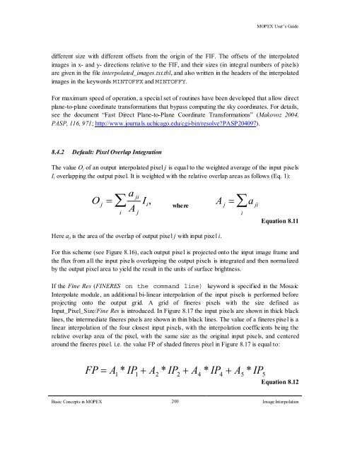
8.4.2 Default: Pixel Overlap Integration<br />
The value Oj of an output interpolated pixel j is equal to the weighted average of the input pixels<br />
Ii overlapping the output pixel. It is weighted with the relative overlap areas as follows (Eq. 1):<br />
a ji<br />
O j = ∑ Ii, where<br />
i<br />
A j<br />
Here aji is the area of the overlap of output pixel j with input pixe l i.<br />
A j = a ji<br />
Basic Concepts in <strong>MOPEX</strong> 200<br />
Image Interpolation<br />
∑<br />
i<br />
Equation 8.11<br />
For this scheme (see Figure 8.16), each output pixel is projected onto the input image frame and<br />
the flux from all the input pixels overlapping the output pixels is integrated and then normalized<br />
by the output pixel area to yield the result in the units of surface brightness.<br />
If the Fine Res (FINERES on the command line) keyword is specified in the Mosaic<br />
Interpolate module, an additional bi-linear interpolation of the input pixels is performed before<br />
projecting onto the output grid. A grid of fineres pixels with the size defined as<br />
Input_Pixel_Size/Fine Res is introduced. In Figure 8.17 the input pixels are shown in thick black<br />
lines, the intermediate fineres pixels are shown in thin black lines. The value of a fineres pixe l is a<br />
linear interpolation of the four closest input pixels, with the interpolation coefficients being the<br />
relative overlap area of the pixel, with the same size as the original input pixe ls, and centered<br />
around the fineres pixel. i.e. the value FP of shaded fineres pixel in Figure 8.17 is equal to:<br />
FP = A 1 * IP 1 + A 2 * IP 2 + A 4 * IP 4 + A 5 * IP 5<br />
Equation 8.12