- Page 2:
Switching Basics and Intermediate R
- Page 6:
Trademark Acknowledgments All terms
- Page 10:
Dedications To my wife Becky, and m
- Page 14:
Contents at a Glance Chapter 1: Int
- Page 18:
Task 16: Configure the Fast Etherne
- Page 22:
DR/BDR Election Exercise 114 Journa
- Page 26:
Comprehensive Lab 2-7: OSPF Configu
- Page 30:
LAN Switches 237 Vocabulary Exercis
- Page 34:
Task 3: Verify Connectivity 283 Tas
- Page 38:
Task 5: Look at the Switches’ Spa
- Page 42:
Task 2: Configure the Hosts Attache
- Page 46:
Challenge Lab 9-6: Advanced Switchi
- Page 50:
Introduction Switching Basics and I
- Page 54:
Work through the Study Guide and La
- Page 58:
CHAPTER 1 Introduction to Classless
- Page 62:
Vocabulary Exercise: Matching Chapt
- Page 66:
Class C Subnetting Scenario Use the
- Page 70:
Prefix Length Use Exercises Use the
- Page 74:
2. 192.168.35.142/29 IP address 110
- Page 78:
4. Use subnet 4 from the last quest
- Page 82:
Figure 1-1 Addressing Design Exerci
- Page 86:
List the address space that is stil
- Page 90:
Figure 1-7 Addressing Design Scenar
- Page 94:
VLSM Addressing Design Scenario 3 C
- Page 98:
Device Interface IP Address Subnet
- Page 102:
For the solution shown in Figure 1-
- Page 106:
First IP 192.168.1.0 11000000.10101
- Page 110:
Figure 1-17 Summary Route Exercise
- Page 114:
Figure 1-19 Summary Route Exercise
- Page 118:
Concept Questions List at least thr
- Page 122:
Figure 1-22 Mom and Pop’s Stop &
- Page 126:
Students should be well versed in u
- Page 130:
Lab Exercises Command Reference In
- Page 134:
Table 1-2 IP Address Range for 192.
- Page 138:
Table 1-8 IP Address Range for 192.
- Page 142:
To finish our visual, we label all
- Page 146:
Task 1: Basic Router Configuration
- Page 150:
Figure 1-29 HyperTerminal Interface
- Page 154:
Task 8: Configure Hostname and Pass
- Page 158:
Task 17: Configure the IP Host Stat
- Page 162:
Curriculum Lab 1-3: Converting RIPv
- Page 166:
BHM(config)#interface serial 0 BHM(
- Page 170:
Curriculum Lab 1-4: Verifying RIPv2
- Page 174:
Task 7: Verify that the Internetwor
- Page 178:
Have they changed now that RIPv2 is
- Page 182:
i - IS-IS, L1 - IS-IS level-1, L2 -
- Page 186:
Redistributing: rip Default version
- Page 190:
The enable, VTY, and console passwo
- Page 194:
policy Policy routing rip RIP proto
- Page 198:
Will the routing table be updated t
- Page 202:
Objectives ■ Review basic router
- Page 206:
Task 3: Verify Connectivity Step 1.
- Page 210:
RTA have a default route. ISP canno
- Page 214:
area E1 - OSPF external type 1, E2
- Page 218:
! logging synchronous login end RTA
- Page 222:
! no shutdown interface Serial0/0 !
- Page 226:
! line con 0 exec-timeout 30 0 pass
- Page 230:
Step 2. Each simulated LAN requires
- Page 234:
C 10.1.8.128 is directly connected,
- Page 238:
RTA(config-if)#ip summary-address r
- Page 242:
Now configure RTB to summarize the
- Page 246:
password cisco logging synchronous
- Page 250:
ip host ISP 209.165.201.1 ip host R
- Page 254:
CHAPTER 2 Single-Area OSPF The Stud
- Page 258:
Vocabulary Exercise: Completion Com
- Page 262:
The term link simply refers to the
- Page 266:
Figure 2-1d Loop-free Topology for
- Page 270:
Learn the OSPF Commands Exercise 1.
- Page 274:
11. The DR/BDR election is based on
- Page 278:
The Cisco IOS uses the 10 8 /bps fo
- Page 282:
Figure 2-6 Propagating a Default Ro
- Page 286:
Network DR/BDR Election? Which Rout
- Page 290:
Command Description Router#show ip
- Page 294:
BERLIN Router>enable Router#configu
- Page 298:
Step 3. Ping from one of the connec
- Page 302:
Table 2-3 Lab Equipment Configurati
- Page 306:
BRASILIA(config-line)#login BRASILI
- Page 310:
Are entries in the routing table? N
- Page 314:
Task 14: Verify OSPF Interface Conf
- Page 318:
Objectives ■ Set up an IP address
- Page 322:
Step 2. Each workstation should be
- Page 326:
Step 2. Examine the running configu
- Page 330:
Step 5. Verify or explain the previ
- Page 334:
Dublin(config-line)#password cisco
- Page 338:
Washington(config)#router ospf 1 Wa
- Page 342:
Curriculum Lab 2-5: Configuring OSP
- Page 346:
Sydney(config)#ip host Rome 192.168
- Page 350:
Task 7: Observe OSPF Traffic Step 1
- Page 354:
After you complete the previous ste
- Page 358:
Task 2: Configure the Area 0 OSPF R
- Page 362:
Task 5: Verify Connectivity Ping fr
- Page 366:
Task 11: Verify Connectivity from t
- Page 370:
Equipment The topology shown in Fig
- Page 374:
Success rate is 100 percent (5/5),
- Page 378:
Number of interfaces in this area i
- Page 382:
no ip domain-lookup ip host RTB 192
- Page 386:
! interface Serial0/1 ! description
- Page 390:
exec-timeout 0 0 password cisco log
- Page 394:
Table 2-16 LAN Addressing Specifica
- Page 398:
login line vty 0 4 ! exec-timeout 0
- Page 402:
hostname REMOTE ! enable secret cla
- Page 406:
CHAPTER 3 EIGRP and Troubleshooting
- Page 410:
Vocabulary Exercise: Completion Dir
- Page 414:
RTA(config)#router eigrp 100 RTA(co
- Page 418:
C 172.16.0.0/18 is directly connect
- Page 422:
In the shaded entry for 192.168.1.1
- Page 426:
Troubleshooting EIGRP Normal EIGRP
- Page 430:
P 172.16.0.0/18, 1 successors, FD i
- Page 434:
It means that this router is runnin
- Page 438:
Internet Research Exercise The CCNA
- Page 442:
Protocol Value Network Layer Protoc
- Page 446:
Curriculum Lab 3-1: Configuring EIG
- Page 450:
PARIS(config-if)#exit PARIS(config)
- Page 454:
Task 6: Configure EIGRP Routing on
- Page 458:
PARIS(config)#line console 0 PARIS(
- Page 462:
Task 5: Configure EIGRP Routing on
- Page 466:
Table 3-5 Addressing Table for Lab
- Page 470:
RTB RTC RTB(config)#interface Loopb
- Page 474:
What command would you configure on
- Page 478:
Step 2. Starting with 10.0.64.0, co
- Page 482:
! ip address 10.0.80.1 255.255.240.
- Page 486:
via 10.0.0.6 (2297856/128256), Seri
- Page 490:
H Address Interface Hold Uptime SRT
- Page 494:
CHAPTER 4 Switching Concepts The St
- Page 498:
Vocabulary Exercise: Matching Defin
- Page 502:
CSMA/CD Process Flow Chart Exercise
- Page 506:
Introduction to LAN Switching In th
- Page 510:
Concept Questions Explain the diffe
- Page 514:
Figure 4-6 Collision and Broadcast
- Page 518:
Lab Exercises There are no Lab Exer
- Page 522:
CHAPTER 5 LAN Design and Switches T
- Page 526:
Vocabulary Exercise: Completion Com
- Page 530:
List and briefly explain the four s
- Page 534:
Figure 5-5 Scenario 4 In Figure 5-5
- Page 538:
Lab Exercises There are no Lab Exer
- Page 542:
CHAPTER 6 Catalyst Switch Configura
- Page 546:
Switch LED Interpretation Exercise
- Page 550:
Figure 6-2 Basic Switch Configurati
- Page 554:
Lab Exercises Command Reference In
- Page 558:
Table 6-1 shows the switch command
- Page 562:
or #show interface ethernet 0/4 Not
- Page 566:
Curriculum Lab 6-2: Basic Switch Co
- Page 570:
interface FastEthernet0/2 no ip add
- Page 574:
Task 4: Examine the Current Running
- Page 578:
Task 5: Set the Access Passwords (1
- Page 582:
Step 3. Set the port speed of inter
- Page 586:
interface FastEthernet0/3 ! interfa
- Page 590:
Step 3. Type the switch IP address
- Page 594:
Task 6: Determine the show mac-addr
- Page 598:
Why did this change from the last d
- Page 602:
Task 5: Determine the MAC Addresses
- Page 606:
Task 10: Verify the Results Verify
- Page 610:
If you are running Windows 2000, ch
- Page 614:
Task 10: Verify the Results Step 1.
- Page 618:
000a.b772.2b44) MTU 1500 bytes, BW
- Page 622:
Task 1: Configure the Switch Config
- Page 626:
All 0100.0cdd.dddd STATIC CPU 1 000
- Page 630:
Step 4. Record the VLAN 1 MAC addre
- Page 634:
Task 17: Exit the Switch Step 1. Ex
- Page 638:
Step 2. After the TFTP server is ru
- Page 642:
(fc1) Copyright 1986-2004 by cisco
- Page 646:
Table 6-8 Lab Equipment Configurati
- Page 650:
Step 3. From the console session in
- Page 654:
! interface FastEthernet0/7 ! inter
- Page 658:
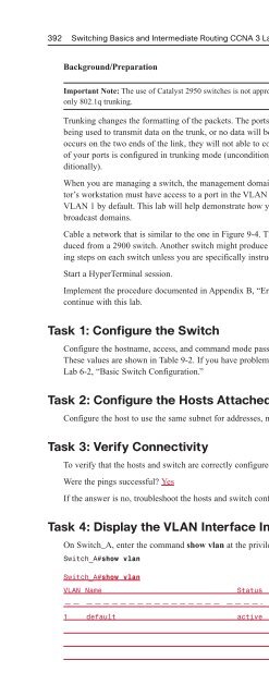
Background/Preparation Cable a netw
- Page 662:
Task 7: Procedure for the 1900 and
- Page 666:
Curriculum Lab 6-10: Firmware Upgra
- Page 670:
Task 5: Prepare for the New Image S
- Page 674:
Equipment The topology shown in Fig
- Page 678:
Step 3. What commands can you use t
- Page 682:
CHAPTER 7 Spanning Tree Protocol Th
- Page 686:
Journal Entry Chapter 7: Spanning T
- Page 690:
Vocabulary Exercise: Completion Com
- Page 694:
Figure 7-2 Determine the Root Bridg
- Page 698:
Figure 7-4 Determine the Root Bridg
- Page 702:
Concept Questions What are the basi
- Page 706:
The enable, VTY, and console passwo
- Page 710:
Task 5: Look at the VLAN Interface
- Page 714:
What is the priority of the non-roo
- Page 718:
Which ports are forwarding on the r
- Page 722:
Objectives ■ Create a basic switc
- Page 726:
hello 2, max age 20, forward delay
- Page 730:
Task 7: Look at the Spanning-Tree T
- Page 734:
———————— ———
- Page 738:
CHAPTER 8 Virtual LANs The Study Gu
- Page 742:
True SWA(config)#interface fa0/4 SW
- Page 746:
VLAN global configuration mode Swit
- Page 750:
Switch#show vlan brief VLAN Name St
- Page 754:
The enable secret password is class
- Page 758:
1002 fddi-default act/unsup 1003 to
- Page 762:
Task 9: Display the VLAN Interface
- Page 766:
VLAN Type SAID MTU Parent RingNo Br
- Page 770:
■ Name the VLANs and assign multi
- Page 774:
Switch_A(config-if)#switchport mode
- Page 778:
VLAN Type SAID MTU Parent RingNo Br
- Page 782:
Why? They have different VLAN membe
- Page 786:
1005 trnet 101005 1500 - - - ibm -
- Page 790: Switch_A(config-if)#switchport acce
- Page 794: Switch_A#show vlan VLAN Name Status
- Page 798: A default VLAN may not be deleted.
- Page 802: 30 Purchasing active Fa0/17, Fa0/18
- Page 806: Total Addresses in System : 0 Max A
- Page 810: ! end SWB !————————
- Page 814: CHAPTER 9 VLAN Trunking Protocol Th
- Page 818: Chapter 9: VLAN Trunking Protocol 3
- Page 822: Vocabulary Exercise: Completion Dir
- Page 826: List and describe the three types o
- Page 830: List three possible ways to reset t
- Page 834: Lab Exercises Command Reference In
- Page 838: Curriculum Lab 9-1: Trunking with I
- Page 844: 394 Switching Basics and Intermedia
- Page 848: 396 Switching Basics and Intermedia
- Page 852: 398 Switching Basics and Intermedia
- Page 856: 400 Switching Basics and Intermedia
- Page 860: 402 Switching Basics and Intermedia
- Page 864: 404 Switching Basics and Intermedia
- Page 868: 406 Switching Basics and Intermedia
- Page 872: 408 Switching Basics and Intermedia
- Page 876: 410 Switching Basics and Intermedia
- Page 880: 412 Switching Basics and Intermedia
- Page 884: 414 Switching Basics and Intermedia
- Page 888: 416 Switching Basics and Intermedia
- Page 892:
418 Switching Basics and Intermedia
- Page 896:
420 Switching Basics and Intermedia
- Page 900:
422 Switching Basics and Intermedia
- Page 904:
424 Switching Basics and Intermedia
- Page 908:
426 Switching Basics and Intermedia
- Page 912:
428 Switching Basics and Intermedia
- Page 916:
430 Switching Basics and Intermedia
- Page 920:
432 Switching Basics and Intermedia
- Page 924:
434 Switching Basics and Intermedia
- Page 928:
436 Switching Basics and Intermedia
- Page 932:
438 Switching Basics and Intermedia
- Page 936:
440 Switching Basics and Intermedia
- Page 940:
442 Switching Basics and Intermedia
- Page 944:
444 Switching Basics and Intermedia
- Page 948:
446 Switching Basics and Intermedia
- Page 952:
448 Switching Basics and Intermedia
- Page 956:
450 Switching Basics and Intermedia
- Page 960:
452 Switching Basics and Intermedia
- Page 964:
454 Switching Basics and Intermedia
- Page 968:
456 Switching Basics and Intermedia
- Page 972:
458 Switching Basics and Intermedia
- Page 976:
460 Switching Basics and Intermedia
- Page 980:
462 Switching Basics and Intermedia
- Page 984:
464 Switching Basics and Intermedia
- Page 988:
466 Switching Basics and Intermedia
- Page 992:
468 Switching Basics and Intermedia
- Page 996:
This page intentionally left blank
- Page 1000:
472 Switching Basics and Intermedia
- Page 1004:
This page intentionally left blank
- Page 1008:
476 Switching Basics and Intermedia
- Page 1012:
478 Switching Basics and Intermedia
- Page 1016:
480 Switching Basics and Intermedia
- Page 1020:
482 Switching Basics and Intermedia
- Page 1024:
484 Switching Basics and Intermedia
- Page 1028:
486 Switching Basics and Intermedia
- Page 1032:
488 Switching Basics and Intermedia
- Page 1036:
490 Switching Basics and Intermedia
- Page 1040:
492 Switching Basics and Intermedia
- Page 1044:
494 Switching Basics and Intermedia
- Page 1048:
496 Switching Basics and Intermedia
- Page 1052:
498 Switching Basics and Intermedia
- Page 1056:
500 Switching Basics and Intermedia
- Page 1060:
502 Switching Basics and Intermedia
- Page 1064:
504 Switching Basics and Intermedia
- Page 1068:
506 Switching Basics and Intermedia
- Page 1072:
508 Switching Basics and Intermedia
- Page 1076:
510 Switching Basics and Intermedia
- Page 1080:
512 Switching Basics and Intermedia
- Page 1084:
514 Switching Basics and Intermedia
- Page 1088:
516 Switching Basics and Intermedia
- Page 1092:
518 Switching Basics and Intermedia
- Page 1096:
520 Switching Basics and Intermedia
- Page 1100:
522 Switching Basics and Intermedia