- Page 1 and 2:
MANUAL DE INSTALAÇÃO E UTILIZAÇ
- Page 3 and 4:
11.- OPÇÃO LIMITADOR DE ALCANCE L
- Page 5 and 6:
1.- DECLARAÇÃO DE CONFORMIDADE (B
- Page 7 and 8:
3.- DESCRIÇÃO DO SISTEMA Os contr
- Page 9 and 10:
4.3 - RECOMENDACIONES FCC (Sólo v
- Page 11 and 12:
5.2 - RECEPTOR Promover a parada to
- Page 13 and 14:
5.3- INÍCIO DE OPERAÇÃO Seja pre
- Page 15 and 16:
6.- UTILIZAÇÃO Para uma correta u
- Page 17 and 18:
7.3 - LOCALIZAÇÃO DE AVARIAS O em
- Page 19 and 20:
ANEXO A - PROGRAMAÇÃO DO EMISSOR
- Page 21 and 22:
ANEXO C - MUDANÇA DE CANAL BASE. O
- Page 23 and 24:
8.1 - INTRODUCCIÓN El equipo TM70
- Page 25 and 26:
100D: LIFE TIME FACTOR 1014: COB-ID
- Page 27 and 28:
8.5 - DICCIONARIO DE DATOS DEL RECE
- Page 29 and 30:
8.6 - SEÑALIZACIÓN El receptor di
- Page 31 and 32:
Mantenimiento y localización de er
- Page 33 and 34:
9.1 - INTRODUCCIÓN y DESCRIPCION F
- Page 35 and 36:
9.3 - EXPLOSIONADO DE ENSAMBLAJE T7
- Page 37 and 38:
9.5 - MODO RETORNO DE INFORMACION L
- Page 39 and 40:
9.5.2 ICONOS DISPONIBLES Los iconos
- Page 41 and 42:
Ejemplo: Retorno CAN VT100 Escribir
- Page 43 and 44:
Una vez completados los 24 caracter
- Page 45 and 46:
10. TM70 - OPERACIONES EN MODO FIRS
- Page 47 and 48:
11.1.1- DESCRIPCIÓN DEL SISTEMA Lo
- Page 49 and 50:
11.2.2 - INSTALACION Y CONEXIONADO
- Page 51 and 52:
11.3.1 - EMISOR INFRARROJO LA70M Nu
- Page 53 and 54:
Area de cobertura elíptica de la e
- Page 55 and 56:
12.- MODO DE FUNCIONAMIENTO “PITC
- Page 57 and 58:
Los emisores no disponen de ningún
- Page 59 and 60:
13. TM70 - OPERACIONES EN TANDEM 13
- Page 61 and 62:
13.3.- SISTEMAS CON DOS EMISORES MA
- Page 63 and 64:
14. TM70 - OPERACIONES CON VIA DE R
- Page 65 and 66:
14.3- MONTAJE EXPANSION IN0-10V CON
- Page 67 and 68: 15.1 - INTRODUCCIÓN y DESCRIPCION
- Page 69 and 70: 16.- OPCION IN4D OPCION IN4D TM70 T
- Page 71 and 72: En caso de no disponer una tensión
- Page 73 and 74: 16.2.- CONEXIÓN CON LR71 y LR72 2.
- Page 75 and 76: 17.1- INTRODUCCION y DESCRIPCION FU
- Page 77 and 78: 18.- OPCION A1P4RCAN OPCION A1P4RCA
- Page 79 and 80: SALIDAS DE RELÉS RL2 RL3 +VI GND 1
- Page 81 and 82: 19.- OPCION A2ICAN OPCION A2ICAN TM
- Page 83 and 84: La velocidad de rampa se define par
- Page 85 and 86: JUMPERS DE CONFIGURACION Tamaño ¼
- Page 87 and 88: 20.1- INTRODUCCIÓN Y DESCRIPCIÓN
- Page 89 and 90: El rango de los valores de salida o
- Page 91 and 92: 20.3- TARJETA DE ALIMENTACIÓN DE E
- Page 93 and 94: 21.1- INTRODUCCIÓN El acceso a est
- Page 95 and 96: (*) SI FREQ. PWM = 0 (ALTA FRECUENC
- Page 97 and 98: VALORES LIMIT: Ajuste de los valore
- Page 99 and 100: 21.2.2- MENU 3.2 VAL. FÁBRICA: Imp
- Page 101 and 102: 22.1 - CARACTERISTICAS PRINCIPALES
- Page 103 and 104: OPCION 4: Relación de tipos de exp
- Page 105 and 106: 22.2 - OBSERVACIONES PARA EL CABLEA
- Page 107 and 108: CHINA 北京市朝阳区望京阜
- Page 109 and 110: I N D I C E 1.- DECLARATION OF CONF
- Page 111 and 112: TM70Pi V3.2 (11/02) 120021.pdf. iii
- Page 113 and 114: 2. - DECLARATION OF CONFORMITY (433
- Page 115 and 116: 4.- SAFETY INSTRUCTIONS These instr
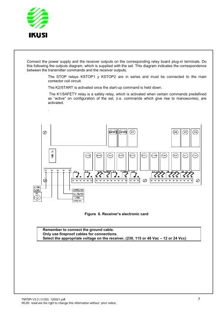
- Page 117: 5.- INSTALLATION 5.1 - CB70 (BC70K)
- Page 121 and 122: Next, turn transmitter ON to OPERAT
- Page 123 and 124: 7.- MAINTENANCE 7.1 - WARRANTY 7.2
- Page 125 and 126: There are also two LEDs in the rece
- Page 127 and 128: ANNEX B.- PROGRAMMING THE MACHINE I
- Page 129 and 130: 8.- CAN OPEN INTERFACE V 2.4 CANope
- Page 131 and 132: The LED signalling is the one recom
- Page 133 and 134: 8.4 - PUSHBUTTONS AND CONSOLE BOX P
- Page 135 and 136: CONSOLE BOX: The receiver can accep
- Page 137 and 138: Connections scheme : Receiver‟s d
- Page 139 and 140: 9.- LCD70 DISPLAY OPTION LCD70 DISP
- Page 141 and 142: 9.2 - INTERNAL CONNECTION POWER SUP
- Page 143 and 144: TM70Pi V3.2 (11/02) 120021.pdf. 31
- Page 145 and 146: 9.5 - DATA FEEDBACK OPERATING MODE
- Page 147 and 148: 9.5.2 AVAILABLE ICONS: The availabl
- Page 149 and 150: Example: VT100 data feedback Write
- Page 151 and 152: Once that we have completed the 24
- Page 153 and 154: TM70 - “FIRST COME - FIRST SERVED
- Page 155 and 156: 11.1.1 - SYSTEM DESCRIPTION TM70 ra
- Page 157 and 158: In cases in which it is believed th
- Page 159 and 160: In cases in which the area covered
- Page 161 and 162: Module: LA70M EX SPECIFICATIONS DC
- Page 163 and 164: 11.3.2.- LA70M INSTALLATION AND CON
- Page 165 and 166: TM70 - “PITCH & CATCH” OPERATIO
- Page 167 and 168: 13.- TANDEM OPERATION TANDEM OPERAT
- Page 169 and 170:
13.2 - ONE MASTER TRANSMITTER SYSTE
- Page 171 and 172:
14.- ANALOGUE FEEDBACK / IN 0-10V O
- Page 173 and 174:
8. Press ―ENTER‖ function. 9. I
- Page 175 and 176:
15.- IN0450P OPTION IN0450P OPTION
- Page 177 and 178:
15.2 - IN0450P and LR70 ASSEMBLY IN
- Page 179 and 180:
16.1 - INTRODUCTION AND FUNCTIONAL
- Page 181 and 182:
Electronic card top view (see figur
- Page 183 and 184:
17.- INCAN OPTION INCAN OPTION TM70
- Page 185 and 186:
RL4 Pin Name Function + +VI DC powe
- Page 187 and 188:
18.1.- INTRODUCTION and FUNCTIONAL
- Page 189 and 190:
ANALOGUE OUTPUT The analogue output
- Page 191 and 192:
19.1- INTRODUCTION & FUNCTIONAL DES
- Page 193 and 194:
OUTPUTS Each analogue output has tw
- Page 195 and 196:
TM70Pi V3.2 (11/02) 120021.pdf. 83
- Page 197 and 198:
20.1- INTRODUCTION & FUNCTIONAL DES
- Page 199 and 200:
OUTPUT 1 (VO1) The connections of t
- Page 201 and 202:
20.3- EXPANSIONS POWER SUPPLY ELECT
- Page 203 and 204:
21.1 - INTRODUCTION Access to this
- Page 205 and 206:
(*) IF PWM FREQ. = 0 (HIGH FREQUENC
- Page 207 and 208:
LIMIT VALUES: Set the limits of the
- Page 209 and 210:
2.2 - MENU 3.2 RESET VALUES: Restor
- Page 211 and 212:
22.1 - MAIN CHARACTERISTICS Softwar
- Page 213 and 214:
OPTION 4: List of expansión type a
- Page 215 and 216:
22.2 - REMARKS FOR THE INTERNAL WIR
- Page 217:
CHINA 北京市朝阳区望京阜