manual de instalação e utilização transmissor console ... - Usicontrol
manual de instalação e utilização transmissor console ... - Usicontrol
manual de instalação e utilização transmissor console ... - Usicontrol

Create successful ePaper yourself
Turn your PDF publications into a flip-book with our unique Google optimized e-Paper software.
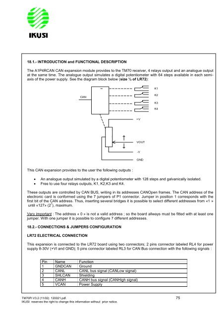
18.1.- INTRODUCTION and FUNCTIONAL DESCRIPTION<br />
The A1P4RCAN CAN expansion module provi<strong>de</strong>s to the TM70 receiver, 4 relays output and an analogue output<br />
at the same time. The analogue output simulates a digital potentiometer with 64 steps available in each semiaxis<br />
of the power supply. See the diagram block below (size ½ of LR72):<br />
CAN<br />
This CAN expansion provi<strong>de</strong>s to the user the following outputs :<br />
An analogue output simulated by a digital potentiometer with 128 steps and galvanically isolated.<br />
Free to use four relays outputs, K1, K2,K3 and K4.<br />
These outputs are controlled by CAN BUS, writing in its addresses CANOpen frames. The CAN address of the<br />
electronic card is conformed using the 7 jumpers of P1 connector. Jumper in position 1 corresponds with the<br />
first bit of the CAN address. Thus, inserting several bridges it is possible to select different addresses from «1 »<br />
until «127» (2 7 ), maximum.<br />
Very important : The address « 0 » is not a valid address ; so the board allways must be fitted with at least one<br />
jumper. With one jumper it is possible to configure 7 different addresses.<br />
18.2.- CONNECTIONS & JUMPERS CONFIGURATION<br />
LR72 ELECTRICAL CONNECTION<br />
This expansion is connected to the LR72 board using two connectors; 2 pins connector labeled RL4 for power<br />
supply 8-30V (+VI and GND); 5 pins connector labeled RL3 for CAN Bus connection with the following signals :<br />
Pin Name Function<br />
1 GNDCAN Ground<br />
2 CANL CANL bus signal (CANLow signal)<br />
3 SHLCAN Shielding<br />
4 CANH CANH bus signal (CANHigh signal)<br />
5 VCAN Power Supply<br />
TM70Pi V3.2 (11/02) 120021.pdf. 75<br />
IKUSI reserves the right to change this information without prior notice.<br />
11k2<br />
+V<br />
VOUT<br />
-V<br />
GND<br />
K1<br />
K2<br />
K3<br />
K4