manual de instalação e utilização transmissor console ... - Usicontrol
manual de instalação e utilização transmissor console ... - Usicontrol
manual de instalação e utilização transmissor console ... - Usicontrol

You also want an ePaper? Increase the reach of your titles
YUMPU automatically turns print PDFs into web optimized ePapers that Google loves.
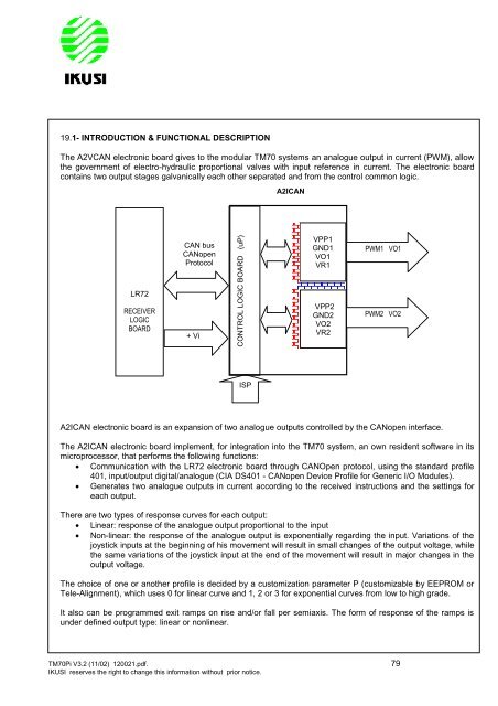
19.1- INTRODUCTION & FUNCTIONAL DESCRIPTION<br />
The A2VCAN electronic board gives to the modular TM70 systems an analogue output in current (PWM), allow<br />
the government of electro-hydraulic proportional valves with input reference in current. The electronic board<br />
contains two output stages galvanically each other separated and from the control common logic.<br />
LR72<br />
RECEIVER<br />
LOGIC<br />
BOARD<br />
CAN bus<br />
CANopen<br />
Protocol<br />
+ Vi<br />
A2ICAN<br />
VPP1<br />
GND1<br />
VO1<br />
VR1<br />
VPP2<br />
GND2<br />
VO2<br />
VR2<br />
PWM1 VO1<br />
A2ICAN electronic board is an expansion of two analogue outputs controlled by the CANopen interface.<br />
The A2ICAN electronic board implement, for integration into the TM70 system, an own resi<strong>de</strong>nt software in its<br />
microprocessor, that performs the following functions:<br />
Communication with the LR72 electronic board through CANOpen protocol, using the standard profile<br />
401, input/output digital/analogue (CIA DS401 - CANopen Device Profile for Generic I/O Modules).<br />
Generates two analogue outputs in current according to the received instructions and the settings for<br />
each output.<br />
There are two types of response curves for each output:<br />
Linear: response of the analogue output proportional to the input<br />
Non-linear: the response of the analogue output is exponentially regarding the input. Variations of the<br />
joystick inputs at the beginning of his movement will result in small changes of the output voltage, while<br />
the same variations of the joystick input at the end of the movement will result in major changes in the<br />
output voltage.<br />
The choice of one or another profile is <strong>de</strong>ci<strong>de</strong>d by a customization parameter P (customizable by EEPROM or<br />
Tele-Alignment), which uses 0 for linear curve and 1, 2 or 3 for exponential curves from low to high gra<strong>de</strong>.<br />
It also can be programmed exit ramps on rise and/or fall per semiaxis. The form of response of the ramps is<br />
un<strong>de</strong>r <strong>de</strong>fined output type: linear or nonlinear.<br />
TM70Pi V3.2 (11/02) 120021.pdf. 79<br />
IKUSI reserves the right to change this information without prior notice.<br />
CONTROL LOGIC BOARD (uP)<br />
ISP<br />
PWM2 VO2