manual de instalação e utilização transmissor console ... - Usicontrol
manual de instalação e utilização transmissor console ... - Usicontrol
manual de instalação e utilização transmissor console ... - Usicontrol

You also want an ePaper? Increase the reach of your titles
YUMPU automatically turns print PDFs into web optimized ePapers that Google loves.
5.3 - STARTING UP<br />
Proceed with caution; the equipment may not be connected correctly which may<br />
lead to unforeseeable movements on starting-up.<br />
Once the receiver has been connected, disconnect the power supply to the motors, (for example, by<br />
removing the fuses) and power on the receiver. First of all the LEDs will light on an instant to test that all are<br />
all right, after this the receiver will enter into a ‗SCANNING‘ mo<strong>de</strong> and the following LED‘s will be lit in the<br />
receiver;<br />
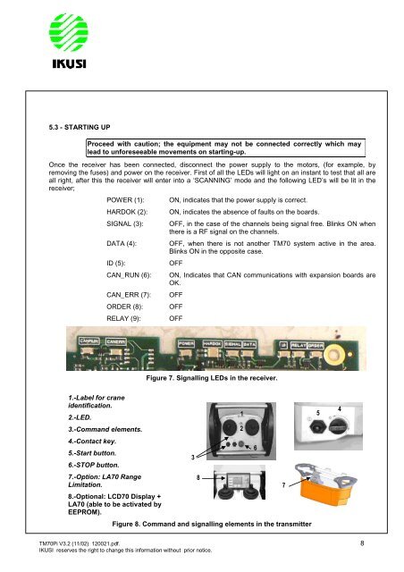
1.-Label for crane<br />
i<strong>de</strong>ntification.<br />
2.-LED.<br />
3.-Command elements.<br />
4.-Contact key.<br />
5.-Start button.<br />
6.-STOP button.<br />
7.-Option: LA70 Range<br />
Limitation.<br />
POWER (1): ON, indicates that the power supply is correct.<br />
HARDOK (2): ON, indicates the absence of faults on the boards.<br />
SIGNAL (3): OFF, in the case of the channels being signal free. Blinks ON when<br />
there is a RF signal on the channels.<br />
DATA (4): OFF, when there is not another TM70 system active in the area.<br />
Blinks ON in the opposite case.<br />
ID (5): OFF<br />
CAN_RUN (6): ON, Indicates that CAN communications with expansion boards are<br />
OK.<br />
CAN_ERR (7): OFF<br />
ORDER (8): OFF<br />
RELAY (9): OFF<br />
8.-Optional: LCD70 Display +<br />
LA70 (able to be activated by<br />
EEPROM).<br />
Figure 7. Signalling LEDs in the receiver.<br />
3<br />
8<br />
Figure 8. Command and signalling elements in the transmitter<br />
TM70Pi V3.2 (11/02) 120021.pdf. 8<br />
IKUSI reserves the right to change this information without prior notice.<br />
1<br />
2<br />
6<br />
7<br />
5<br />
4