manual de instalação e utilização transmissor console ... - Usicontrol
manual de instalação e utilização transmissor console ... - Usicontrol
manual de instalação e utilização transmissor console ... - Usicontrol

You also want an ePaper? Increase the reach of your titles
YUMPU automatically turns print PDFs into web optimized ePapers that Google loves.
In or<strong>de</strong>r to return to the operating mo<strong>de</strong>, all the worker has to do is move back into the working zone.<br />
Movement or<strong>de</strong>rs must be disabled in or<strong>de</strong>r to restart movement. Once the transmitter enters the<br />
working area, movement or<strong>de</strong>rs will not be ready to be used unless they have gone to zero. This is to<br />
make movements start in first speed. If the remote control is provi<strong>de</strong>d with a Display, whenever the<br />
transmitter is out of range, the message ―Out of Range‖ will be displayed.<br />
The remote control has got 4 mo<strong>de</strong>s of operation <strong>de</strong>fined in the EEPROM:<br />
1.- Range Limiter only at start up (Electronic Key): In or<strong>de</strong>r to make the transmitter work, it is<br />
necessary that the transmitter is insi<strong>de</strong> the starting zone, <strong>de</strong>fined by the position of the infrared<br />
transmitter.<br />
2.- Range Limiter only in operation: The transmitter can be started anywhere insi<strong>de</strong> or outsi<strong>de</strong> of the<br />
working area, but the movement or<strong>de</strong>rs will not work until the transmitter is insi<strong>de</strong> the working zone.<br />
3.- Range Limiter at startup and operation: The transmitter in or<strong>de</strong>r to work must be insi<strong>de</strong> the working<br />
zone always.<br />
4.- Range Limiter only as an output Relay: This functionality makes the transmitter not to show In<br />
range or Out of range situation in the transmitter itself. It will not mask any or<strong>de</strong>r. The information will<br />
be sent to the receiver in or<strong>de</strong>r to process the information as an output relay or a condition to the relay<br />
table.<br />
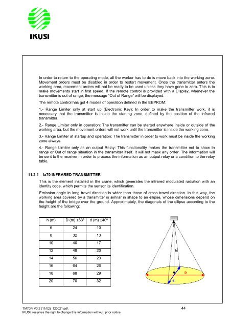
11.2.1 – la70 INFRARED TRANSMITTER<br />
This is the element installed in the crane, which generates the infrared modulated radiation with an<br />
i<strong>de</strong>ntity co<strong>de</strong>, which permits the sensor its i<strong>de</strong>ntification.<br />
Emission angle in long travel direction is wi<strong>de</strong>r than those of cross travel direction. In this way, the<br />
working area covered by a transmitter is similar in shape to an ellipse, whose dimensions <strong>de</strong>pend on<br />
the height of the bridge over the ground. Approximately, the diagonals of the ellipse according to the<br />
height are the following:<br />
h (m) D (m) ±63º d (m) ±40º<br />
6 24 10<br />
8 32 13<br />
10 40 17<br />
12 48 20<br />
14 56 23<br />
16 64 26<br />
18 68 29<br />
20 70 32<br />
TM70Pi V3.2 (11/02) 120021.pdf. 44<br />
IKUSI reserves the right to change this information without prior notice.