OS 75x100 mm.pdfTélécharger - KWH Mirka Ltd
OS 75x100 mm.pdfTélécharger - KWH Mirka Ltd
OS 75x100 mm.pdfTélécharger - KWH Mirka Ltd

You also want an ePaper? Increase the reach of your titles
YUMPU automatically turns print PDFs into web optimized ePapers that Google loves.
2. Lightly grease (36) O-Ring and place it on the (37) Speed<br />
Control. Install (35) Valve Stem, (36) O-Ring (cleaned and<br />
lightly greased) and insert the Speed Control into (33) Housing<br />
in the midway position. Install (38) Retaining Ring.<br />
Caution: Make sure the (38) Retaining Ring is completely<br />
snapped into groove in the (33) Housing.<br />
3. Install the (49) Seat, the (50) Valve and (51) Spring. Coat the<br />
threads of the (52) Bushing Assembly with 1 or 2 drops of<br />
Loctite® 222 or equivalent non-permanent pipe thread sealant.<br />
Screw the assembly into the (33) Housing. See “Parts<br />
Page” for torque settings.<br />
Note: If the machine is a vacuum model, proceed with the appropriate<br />
vacuum exhaust assembly instructions, otherwise please<br />
continue.<br />
4. Place a clean (48) Muffler and the (47) Plate into the exhaust<br />
port of the (33) Housing.<br />
5. Place a clean (46) Muffler in the (48) Muffler Housing and<br />
screw the Muffler Housing into the exhaust port of the (33)<br />
Housing. See “Parts Page” for torque settings.<br />
6. Install the (53) Snap-In Vacuum Cover Plate.<br />
For CV exhaust machines:<br />
A. Attach the (54) Snap-In Exhaust Adapter.<br />
B. Take the (65) Ø 1 in./28 <strong>mm</strong> SuperVAC CV Swivel Exhaust<br />
Assembly or the (64) Ø ¾ in./19 <strong>mm</strong> SuperVAC CV Swivel<br />
Exhaust Assembly and put the “tongue” on the male end of it<br />
into the female end of the (54) Snap-In Exhaust Adapter. With<br />
the swivel end of the SuperVAC Exhaust angled towards<br />
the ground work the “tongue” and male end into the female<br />
end of the Snap-In Exhaust Adapter by rotating the swivel<br />
end up and in at the same time until it seats.<br />
C. Place the (66) Nut into the cavity of the Housing. Place the<br />
(67) Washer onto (68) Screw and insert into the mounting<br />
hole of the (65) Ø 1 in./28 <strong>mm</strong> SuperVAC CV Swivel<br />
Exhaust Assembly or the (64) Ø ¾ in./19 <strong>mm</strong> SuperVAC<br />
CV Swivel Exhaust Assembly and (33) Housing. See “Parts<br />
Page” for torque settings.<br />
D. Place a clean (46) Muffler and the (47) Plate into the exhaust<br />
port of the (33) Housing.<br />
E. Place a clean (46) Muffler in the (48) Muffler Housing and<br />
screw the Muffler Housing into the exhaust port of the (33)<br />
Housing. See “Parts Page” for torque settings<br />
For SGV exhaust machines:<br />
A. Attach the (54) Snap-In Exhaust Adapter.<br />
B. Lightly grease two (56) O-Rings and place them over the two<br />
grooves in the (55) SGV Retainer Assembly. Slide the SGV<br />
Retainer Assembly into the bore of the (57) Ø 1 in./28 <strong>mm</strong><br />
SGV Swivel Exhaust Assembly or the (58) Ø ¾ in./19 <strong>mm</strong><br />
Hose SGV Swivel Exhaust Assembly.<br />
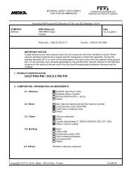
Press Tool Top<br />
(MPA0202)<br />
Press Tool Base<br />
(MPA0201)<br />
Bearing (20)<br />
Shim (21)<br />
Dust Shield (72)<br />
Washer (22)<br />
Spindle (24)<br />
9<br />
C. Attach the (55) SGV Swivel Exhaust Assembly to the exhaust<br />
port of the (33) Housing by means of the SGV Retainer<br />
Assembly and by taking the male end of the SGV Swivel<br />
Exhaust Assembly and placing it into the female end of the<br />
(54) Snap-In Exhaust Adapter. Screw the SGV Retainer<br />
Assembly into the threaded exhaust port on the Housing with<br />
an (MPA0849) 8 <strong>mm</strong> Hex Key Wrench. See “Parts Page” for<br />
torque settings. Move onto the section “Spindle, AirSHIELD<br />
and Balancer Shaft Assembly”.<br />
Spindle, AirSHIELD and Balancer Shaft Assembly:<br />
1. Place the (MPA0201) T-2A Spindle Bearing Pressing Tool<br />
Base onto a flat, clean surface of a small hand press or<br />
equivalent with the spindle pocket facing upward. Place the<br />
(24) Spindle into the spindle pocket with the shaft facing<br />
upward. See Figure 3.<br />
2. Place the (22) Washer on the (24) Spindle shaft with the<br />
curve of the Washer facing up so that the outside diameter of<br />
the Washer will contact the outer diameter of the (20) Bearing.<br />
Place the (72) Dust Shield onto the Spindle shaft. Place<br />
the (21) Shim onto the shoulder of the Spindle. Note: Be<br />
sure that the Dust Shield is past the shoulder where Spacer<br />
rests. Place the Bearing (one seal) on the Spindle with the<br />
seal side toward the Washer. Note: Make sure that both the<br />
inner and outer races of the Bearings are supported by the<br />
Bearing Press Tool when pressing them into place. Press the<br />
Bearing onto the shoulder of Spindle using the (MPA0202)<br />
T-2B Spindle Bearing Pressing Tool Top as shown in Figure<br />
3.<br />
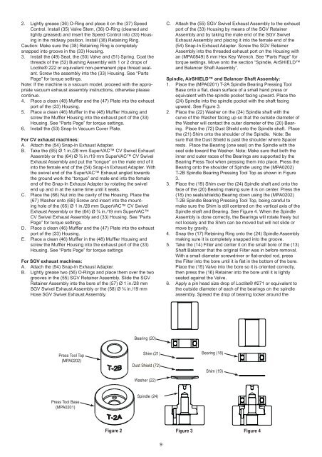
3. Place the (19) Shim over the (24) Spindle shaft and onto the<br />
face of the (20) Bearing making sure it is on center. Press the<br />
(18) (no seals/shields) Bearing down using the (MPA0202)<br />
T-2B Spindle Bearing Pressing Tool Top, being careful to<br />
make sure the Shim is still centered on the vertical axis of the<br />
Spindle shaft and Bearing. See Figure 4. When the Spindle<br />
Assembly is done correctly, the Bearings will rotate freely but<br />
not loosely and the Shim can be moved but will not slide or<br />
move by gravity.<br />
4. Snap the (17) Retaining Ring onto the (24) Spindle Assembly<br />
making sure it is completely snapped into the groove.<br />
5. Take the (14) Filter and center it on the small bore of the (13)<br />
Shaft Balancer that the original Filter was in before removal.<br />
With a small diameter screwdriver or flat-ended rod, press<br />
the Filter into the bore until it is flat in the bottom of the bore.<br />
Place the (15) Valve into the bore so it is oriented correctly,<br />
then press the (16) Retainer into the bore until it is lightly<br />
seated against the Valve.<br />
6. Apply a pin head size drop of Loctite® #271 or equivalent to<br />
the outside diameter of each of the bearings on the spindle<br />
assembly. Spread the drop of bearing locker around the<br />
Bearing (18)<br />
Shim (19)<br />
Figure 2 Figure 3<br />
Figure 4