ROS 125 150 mm.pdfTélécharger - Mirka
ROS 125 150 mm.pdfTélécharger - Mirka
ROS 125 150 mm.pdfTélécharger - Mirka

Create successful ePaper yourself
Turn your PDF publications into a flip-book with our unique Google optimized e-Paper software.
Seat, (28) Valve Stem and (29) O-Ring.<br />
4. Press out the (24) Spring Pin from the (27) Housing and<br />
remove the (23) Throttle Lever.<br />
ASSEMBLY INSTRUCTIONS<br />
NOTE: All assembly must be done with clean dry parts and all<br />
bearings are to be pressed in place by the correct tools and<br />
procedures as outlined by the bearing manufacturers.<br />
Housing Assembly:<br />
1. Install (23) Throttle Lever into (27) Housing with the (24)<br />
Spring Pin.<br />
2. Lightly grease the (29) O-Ring and place it on the (30) Speed<br />
Control. Install (28) Valve Stem, O-Ring (cleaned and lightly<br />
greased) and insert the Speed control into the (27) Housing<br />
in the midway position. Install the (31) Retaining Ring. CAU-<br />
TION: Make sure the Retaining Ring is completely snapped<br />
into groove in the Housing.<br />
3. Install the (40) Valve Seat, the (41) Valve and the (42) Valve<br />
Spring. Coat the threads of the (43) Bushing Assembly with 1<br />
or 2 drops of Loctite® 222 or equivalent non-permanent pipe<br />
thread sealant. Screw the assembly into the (27) Housing.<br />
Torque to 6.77 Nm (60 in/lbs).<br />
4. For NV and CV machines follow the steps outlined in Section<br />
I below. For SGV machines follow the steps in Section III.<br />
I. This section is for CV and NV<br />
A) Place a clean (37) felt Muffler all-the-way into the chamber<br />
of the (43) Muffler Housing. Press the muffler onto the (39)<br />
Muffler Housing.<br />
B) Screw the (39) Muffler Housing assembly into the (27)<br />
Housing until hand tight. Use a 21 <strong>mm</strong> socket/torque wrench<br />
combination to torque the (39) Muffler Housing. Torque to<br />
2.25Nm (20 in/lbs ). For NV machines move onto C. For CV<br />
machines move onto Section II.<br />
C) Install the (32) Non-Vacuum Shroud onto the (27) Housing by<br />
working the shroud over and around the bottom of the housing<br />
flanges. Make sure the line up slots (on the Housing) and<br />
tabs (on the Shroud) are engaged. Move onto the ”Spindle,<br />
AirSHIELD and Shaft Balancer Assembly” Section.<br />
II. This section continued from Section I for CV Exhaust<br />
machines:<br />
A) Install the (33 or 34) Shroud onto the (27) Housing by work<br />
ing the shroud over and around the bottom of the housing<br />
flanges. Slide the inlet end of the (54) CV Swivel Exhaust<br />
Assembly into the exhaust port of the (33 or 34) Shroud until<br />
it hits the stop on the Swivel Exhaust Assembly.<br />
NOTE: For installation of Shrouds and Skirts make sure the line<br />
up slots (on the Housing) and tabs (on the Shroud or Skirt) are<br />
engaged. Make sure that the key on the Swivel Exhaust Assembly<br />
bracket is aligned and engaged with the keyway on the Housing.<br />
B) Place the (57) Washer over the (58) Screw. Thread the screw<br />
into the mounting hole of the (55 or 53) Swivel Exhaust Assembly<br />
and (27) Housing until the end of the screw is flush<br />
with the inside surface of the Housing. Place the (55) Nut into<br />
the cavity of the Housing and thread the Screw into the Nut<br />
until tight. Move onto the “Spindle, AirSHIELD and Shaft<br />
Balancer Assembly” Section.<br />
III. This section for SGV Exhaust machines:<br />
A) Install the (33 or 34) Shroud onto the (27) Housing by working<br />
the shroud or skirt over and around the bottom of the<br />
housing flanges. Make sure the line up slots (on the Housing)<br />
and tabs (on the Shroud or Skirt) are engaged.<br />
B) Attach the (51) SGV Shroud Adapter to the exhaust port of<br />
the Shroud.<br />
C) Clean and lightly grease the two (44) O-Rings and place<br />
them in the two grooves in the (45) SGV Retainer.<br />
D) Put the (45) SGV Retainer into the mounting hole of the (47)<br />
Hose SGV Swivel Exhaust Assembly.<br />
E) Push the Hose SGV Swivel Exhaust Assembly into the<br />
exhaust port of the SGV Shroud Adapter. Screw the SGV<br />
Retainer into the threaded exhaust port on the Housing with a<br />
MPA0849 8 <strong>mm</strong> Hex Wrench. Torque to 5.08 Nm (45 in/lbs)<br />
Spindle, AirSHIELD and Shaft Balancer Assembly:<br />
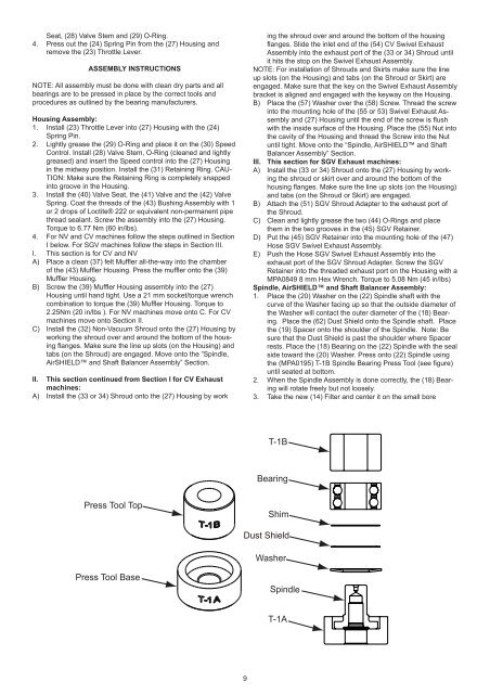
1. Place the (20) Washer on the (22) Spindle shaft with the<br />
curve of the Washer facing up so that the outside diameter of<br />
the Washer will contact the outer diameter of the (18) Bearing.<br />
Place the (62) Dust Shield onto the Spindle shaft. Place<br />
the (19) Spacer onto the shoulder of the Spindle. Note: Be<br />
sure that the Dust Shield is past the shoulder where Spacer<br />
rests. Place the (18) Bearing on the (22) Spindle with the seal<br />
side toward the (20) Washer. Press onto (22) Spindle using<br />
the (MPA0195) T-1B Spindle Bearing Press Tool (see figure)<br />
until seated at bottom.<br />
2. When the Spindle Assembly is done correctly, the (18) Bearing<br />
will rotate freely but not loosely.<br />
3. Take the new (14) Filter and center it on the small bore<br />
T-1B<br />
Bearing<br />
Press Tool Top<br />
Shim<br />
Dust Shield<br />
Washer<br />
Press Tool Base<br />
Spindle<br />
T-1A<br />
9