

General Information on Track Circuits - RGS Online
General Information on Track Circuits - RGS Online
General Information on Track Circuits - RGS Online

Create successful ePaper yourself
Turn your PDF publications into a flip-book with our unique Google optimized e-Paper software.
<str<strong>on</strong>g>General</str<strong>on</strong>g> <str<strong>on</strong>g>Informati<strong>on</strong></str<strong>on</strong>g> <strong>on</strong> <strong>Track</strong> <strong>Circuits</strong><br />
17 Aluminium Busbars<br />
Withdrawn Document<br />
Unc<strong>on</strong>trolled When Printed<br />
400<br />
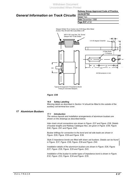
Figure E36<br />
Sleeper Drilled 18 <strong>on</strong> Centre Line X 95 Deep (Min) Metal<br />
Anchor HSL M12/25 Hilti Code 6692 2 Off<br />
M20 X 50 L<strong>on</strong>g Hex. Hd. Screw<br />
Sleeper Not To Be Drilled<br />
Typical Arrangement if Impedance B<strong>on</strong>d<br />
Fixing to C<strong>on</strong>crete Sleepers<br />
Railway Group Approved Code of Practice<br />
GK/RC0752<br />
Issue Two<br />
Date December 1998<br />
Page E37 of 52<br />
3 X 45 degree Chamfer<br />
40 65<br />
140<br />
3 Fillet Weld<br />
7.5 Radius<br />
All Dimensi<strong>on</strong>s in mm<br />
16.6 Safety Labelling<br />
Warning labels as described in Secti<strong>on</strong> 14 should be fitted to the outside of the<br />
auxiliary coil terminal box cover.<br />
17.1 Introducti<strong>on</strong><br />
The various layouts and installati<strong>on</strong> arrangements of aluminium busbars are<br />
shown <strong>on</strong> the drawings as described below:<br />
Inter–track circuit c<strong>on</strong>necti<strong>on</strong>s are shown in Figure E37 and Figure E38. Details<br />
of busbar lengths and Railway Catalogue Nos. are given in Figure E39, Figure<br />
E40, Figure E41 and Figure E42.<br />
Busbar drillings for c<strong>on</strong>necti<strong>on</strong> to the b<strong>on</strong>d and rail side leads are shown in<br />
Figure E28, Figure E29 and Figure E39.<br />
Style S impedance b<strong>on</strong>ds are fitted with down–set busbars. Details can be found<br />
in Figure E37, Figure E38, Figure E39 and Figure E40.<br />
Installati<strong>on</strong> details of the aluminium busbars are shown in Figure E26, Figure<br />
E27, Figure E28, Figure E29 and Figure E43.<br />
Installati<strong>on</strong> of the busbar to earlier types of impedance b<strong>on</strong>d is shown in Figure<br />
E32, Figure E33, Figure E34 and Figure E35.<br />
R A I L T R A C K E 37<br />
Ø 16<br />
18<br />
30<br />
12<br />
"<br />
40<br />
"


