

General Information on Track Circuits - RGS Online
General Information on Track Circuits - RGS Online
General Information on Track Circuits - RGS Online

You also want an ePaper? Increase the reach of your titles
YUMPU automatically turns print PDFs into web optimized ePapers that Google loves.
<str<strong>on</strong>g>General</str<strong>on</strong>g> <str<strong>on</strong>g>Informati<strong>on</strong></str<strong>on</strong>g> <strong>on</strong> <strong>Track</strong> <strong>Circuits</strong><br />
CL<br />
200<br />
200<br />
Withdrawn Document<br />
Unc<strong>on</strong>trolled When Printed<br />
Railway Group Approved Code of Practice<br />
GK/RC0752<br />
Issue Two<br />
Date December 1998<br />
Page E31 of 52<br />
After installati<strong>on</strong>, it is particularly important to ensure that all glands are securely<br />
tightened <strong>on</strong>to the cables and that all unused entry holes are properly sealed.<br />
This will reduce the incidence of failures resulting from an accumulati<strong>on</strong> of brake<br />
dust <strong>on</strong> the terminal block and tuning capacitor.<br />
Debris exclusi<strong>on</strong> covers should be fitted to Type 3 b<strong>on</strong>ds:<br />
For WBS WH3 Railway Catalogue No 86/17030<br />
For Howells WH3 Railway Catalogue No 86/17031<br />
Note Under no circumstances may a b<strong>on</strong>d be commissi<strong>on</strong>ed unless all glands<br />
are correctly fitted and any unused holes are fitted with a threaded<br />
blanking plate.<br />
For drilling of holes in c<strong>on</strong>crete sleepers/bearers, see GK/RC0754 Part D.<br />
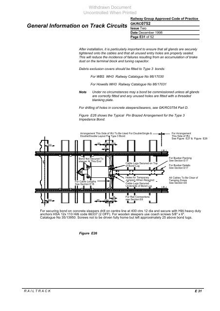
Figure E26 shows the Typical Pin Brazed Arrangement for the Type 3<br />
Impedance B<strong>on</strong>d.<br />
Arrangement This Side of IRJ To Be Used For Double/Single &<br />
Double/Double Layout For Type 3 B<strong>on</strong>d<br />
B<strong>on</strong>d Not Secured To<br />
sleeper At This End<br />
For Cable Lengths<br />
See Secti<strong>on</strong> E18<br />
85 240<br />
85<br />
85 240<br />
200<br />
85<br />
200<br />
Cable Lugs Secured <strong>on</strong> Top<br />
of B<strong>on</strong>d Lug<br />
Holes for Temporary<br />
Jumpers When Required<br />
Cable Lugs Secured<br />
Underside of B<strong>on</strong>d Lug<br />
For Rail C<strong>on</strong>necti<strong>on</strong>s<br />
see Secti<strong>on</strong> E8<br />
R A I L T R A C K E 31<br />
I.R.J.<br />
For Arrangement<br />
This Side of IRJ<br />
See Figure E27 & Figure E28<br />
For Busbar Packing<br />
See Secti<strong>on</strong> E17<br />
For Busbar Details<br />
See Secti<strong>on</strong> E17<br />
All Cables To Be Clear of<br />
Tamping Z<strong>on</strong>es<br />
See Secti<strong>on</strong> E6<br />
I.R.J.<br />
For securing b<strong>on</strong>d <strong>on</strong> c<strong>on</strong>crete sleepers drill <strong>on</strong> centre line at 400 ctrs 12 dia and secure with Hilti heavy duty<br />
anchors HSA 12x 110 Hilti code 66337 (2 OFF). For wooden sleepers use coach screws 5/8" x 6".<br />
Catalogue No 35/13950. Screws not to be driven fully home but left approximately 25 above b<strong>on</strong>d lugs.<br />
Figure E26


