

General Information on Track Circuits - RGS Online
General Information on Track Circuits - RGS Online
General Information on Track Circuits - RGS Online

Create successful ePaper yourself
Turn your PDF publications into a flip-book with our unique Google optimized e-Paper software.
Railway Group Approved Code of Practice<br />
GK/RC0752<br />
Issue Two<br />
Date December 1998<br />
Page E34 of 52<br />
Withdrawn Document<br />
Unc<strong>on</strong>trolled When Printed<br />
<str<strong>on</strong>g>General</str<strong>on</strong>g> <str<strong>on</strong>g>Informati<strong>on</strong></str<strong>on</strong>g> <strong>on</strong> <strong>Track</strong> <strong>Circuits</strong><br />
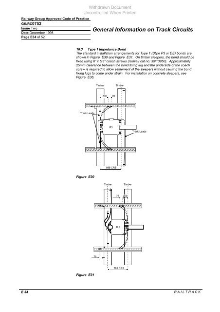
16.3 Type 1 Impedance B<strong>on</strong>d<br />
The standard installati<strong>on</strong> arrangements for Type 1 (Style P3 or DE) b<strong>on</strong>ds are<br />
shown in Figure E30 and Figure E31. On timber sleepers, the b<strong>on</strong>d should be<br />
fixed using 6” x 5/8” coach screws (railway cat no: 35/13950). Approximately<br />
25mm clearance between the b<strong>on</strong>d fixing lug and the underside of the coach<br />
screw is required to allow settlement of the sleepers without causing the b<strong>on</strong>d<br />
fixing lugs to come under strain. For installati<strong>on</strong> <strong>on</strong> c<strong>on</strong>crete sleepers, see<br />
Figure E36.<br />
<strong>Track</strong> Leads<br />
Figure E30<br />
Figure E31<br />
76<br />
Timber Timber<br />
200<br />
P3<br />
585 CRS<br />
E 34 R A I L T R A C K<br />
76<br />
Timber Timber<br />
76<br />
D.E.<br />
585 CRS<br />
200<br />
<strong>Track</strong> Leads


