

General Information on Track Circuits - RGS Online
General Information on Track Circuits - RGS Online
General Information on Track Circuits - RGS Online

You also want an ePaper? Increase the reach of your titles
YUMPU automatically turns print PDFs into web optimized ePapers that Google loves.
<str<strong>on</strong>g>General</str<strong>on</strong>g> <str<strong>on</strong>g>Informati<strong>on</strong></str<strong>on</strong>g> <strong>on</strong> <strong>Track</strong> <strong>Circuits</strong><br />
8 Train Shunt<br />
Imperfecti<strong>on</strong><br />
Withdrawn Document<br />
Unc<strong>on</strong>trolled When Printed<br />
Railway Group Approved Code of Practice<br />
GK/RC0752<br />
Issue Two<br />
Date December 1998<br />
Page B9 of 25<br />
The minimum permitted drop shunt resistance is 0.5Ω (0.3Ω <strong>on</strong> certain<br />
impedance b<strong>on</strong>d track circuits). During very dry weather or severe frost<br />
c<strong>on</strong>diti<strong>on</strong>s, the ballast resistance increases towards its natural maximum and will<br />
offer <strong>on</strong>ly a small c<strong>on</strong>tributi<strong>on</strong> towards the overall shunt. Thus, when a 0.5Ω<br />
(0.3Ω) shunt is placed across the rails, it must still reduce the relay voltage to<br />
below drop–away value.<br />
It should also be noted that the track relay is dropped by short circuit rather than<br />
disc<strong>on</strong>necti<strong>on</strong>. Therefore, the drop–away time of the relay is increased due to<br />
the inductive circuit prol<strong>on</strong>ging the decay of the coil current.<br />
7.3 Principles of Basic Adjustment<br />
The difficulty with adjusting track circuits (where such adjustment is provided) is<br />
knowing the prevailing value of ballast resistance. Details entered <strong>on</strong> the track<br />
circuit record card provide a useful history. These vary with track circuit type<br />
and the appropriate Code of Practice within the <strong>Track</strong> Circuit Handbook should<br />
be c<strong>on</strong>sulted.<br />
Assuming average c<strong>on</strong>diti<strong>on</strong>s, the feed resistance is adjusted to obtain a relay<br />
voltage in the range 25% to 75% above the pick–up value whilst maintaining the<br />
drop shunt resistance at a value greater than the minimum required. If the track<br />
circuit fails due to wet weather, it may be possible to remedy the situati<strong>on</strong> by<br />
reducing the feed resistance. It is important that the track circuit is re–tested<br />
after it has dried out.<br />
The energy seen by the relay with a train <strong>on</strong> the track circuit will depend up<strong>on</strong><br />
the resistive value of the train shunt (see Figure B6). This energy will be zero<br />
<strong>on</strong>ly when the train shunt is zero. Whilst the ohmic resistance of an axle and<br />
wheels is virtually zero, there are a number of factors that can make the<br />
effective train shunt much higher. Since some factors are track based, whilst<br />
others are vehicle specific, the precise mixture of factors applying to a particular<br />
vehicle at a particular place can be very variable.<br />
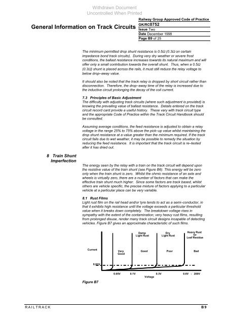
8.1 Rust Films<br />
Light rust film <strong>on</strong> the rail head and/or tyre tends to act as a semi–c<strong>on</strong>ductor, in<br />
that it exhibits high resistance until the voltage exceeds a particular threshold<br />
value when it breaks down completely. The breakdown voltage rises in<br />
sympathy with the extent of the c<strong>on</strong>taminati<strong>on</strong>; very heavy rust films, resulting<br />
from prol<strong>on</strong>ged disuse, render many track circuit designs incapable of detecting<br />
vehicles. Figure B7 gives an approximate characteristic of such films.<br />
Current<br />
0.01V<br />
Figure B7<br />
RAILTRACK B9<br />
Very<br />
Good<br />
Damp<br />
Light Rust<br />
Dry<br />
Light Rust<br />
Heavy Rust<br />
Or<br />
Leaf Residue<br />
Good Poor Bad<br />
0.05V 0.1V 0.3V 0.6V - 200V<br />
Voltage


