

General Information on Track Circuits - RGS Online
General Information on Track Circuits - RGS Online
General Information on Track Circuits - RGS Online

Create successful ePaper yourself
Turn your PDF publications into a flip-book with our unique Google optimized e-Paper software.
Withdrawn Document<br />
Unc<strong>on</strong>trolled When Printed<br />
<str<strong>on</strong>g>General</str<strong>on</strong>g> <str<strong>on</strong>g>Informati<strong>on</strong></str<strong>on</strong>g> <strong>on</strong> <strong>Track</strong> <strong>Circuits</strong><br />
Railway Group Approved Code of Practice<br />
GK/RC0752<br />
Issue Two<br />
Date December 1998<br />
Page E49 of 52<br />
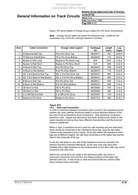
Figure E51 gives details of Orange Group Cables (For Pin Drive C<strong>on</strong>necti<strong>on</strong>s).<br />
Note Orange Group cables are shown for reference <strong>on</strong>ly – preferred rail<br />
c<strong>on</strong>necti<strong>on</strong> is by 12mm dia. stud (pin brazed or Cembre).<br />
Item Cable C<strong>on</strong>necti<strong>on</strong> Orange Label Legend Catalogue<br />
No<br />
Length<br />
(mm)<br />
Lug<br />
Types<br />
1 P3 B<strong>on</strong>d to Rail Top P3 to Pin Drive Top 88/29477 765 B & H<br />
2 P3 B<strong>on</strong>d to Rail Bottom P3 to Pin Drive Bottom 88/29476 715 B & H<br />
3 Busbar to Rail L<strong>on</strong>g Busbar to Pin Drive L<strong>on</strong>g N/A 1070 C & A<br />
4 Busbar to Rail Short Busbar to Pin Drive Short N/A 690 C & A<br />
5 M B<strong>on</strong>d to Rail Top M to Pin Drive Top 88/29475 765 D & D<br />
6 M B<strong>on</strong>d to Rail Bottom M to Pin Drive Bottom 88/29474 715 D & D<br />
7 M2, 5 & 6 B<strong>on</strong>d to Rail Top M2, 5, 6 to Pin Drive Top 88/29473 685 D & A<br />
8 M2, 5 & 6 B<strong>on</strong>d to Rail Bottom M2, 5, 6 to Pin Drive Bottom 88/29472 660 D & A<br />
9 B B<strong>on</strong>d to Rail Top B to Pin Drive Top 88/29471 690 F & A<br />
10 B B<strong>on</strong>d to Rail Bottom B to Pin Drive Bottom 88/29470 690 F & A<br />
11 DE B<strong>on</strong>d to Rail DE to Pin Drive 88/29469 765 C & A<br />
12 DD B<strong>on</strong>d to Rail DD to Pin Drive 88/29468 485 C & A<br />
13 S or MR B<strong>on</strong>d to Rail S or MR to Pin Drive 88/29467 740 G & A<br />
14 Busbar to Pin Drive Busbar to Pin Drive 88/27723 800 G & H<br />
Figure E51<br />
18.2 Side Lead C<strong>on</strong>necti<strong>on</strong><br />
In order to minimise imbalance of tracti<strong>on</strong> return current in the impedance b<strong>on</strong>d<br />
tracti<strong>on</strong> coil, every attempt should be made to ensure electrical balance of the<br />
two sets of rail to impedance b<strong>on</strong>d c<strong>on</strong>necti<strong>on</strong>s. Only aluminium c<strong>on</strong>ductors<br />
should be used. Copper and aluminium side leads should not be mixed <strong>on</strong> the<br />
same impedance b<strong>on</strong>d as they have different characteristics and the b<strong>on</strong>d will<br />
become unbalanced.<br />
When a Type 3 impedance b<strong>on</strong>d is used at a site requiring <strong>on</strong>ly two side leads<br />
these should be c<strong>on</strong>nected to the impedance b<strong>on</strong>d lugs using the two holes<br />
nearest to the impedance b<strong>on</strong>d casing. At all sites where the impedance b<strong>on</strong>d<br />
lugs are at different heights, the side lead c<strong>on</strong>necti<strong>on</strong>s to the higher lug must be<br />
fixed to the underside of the lug.<br />
If <strong>on</strong>ly the side leads <strong>on</strong> <strong>on</strong>e side of the impedance b<strong>on</strong>d are renewed, the<br />
balance should be checked afterwards, as the new <strong>on</strong>es may have been<br />
installed with a high resistance or the existing leads <strong>on</strong> the other side may not be<br />
as good as the new <strong>on</strong>es.<br />
Before any c<strong>on</strong>necti<strong>on</strong>s are made to the aluminium plate, any burrs or<br />
protrusi<strong>on</strong>s should be removed from the mating surfaces of the plate, lug,<br />
washers and nuts. A wire brush or steel wool should then be used to make<br />
these surfaces clean and bright.<br />
R A I L T R A C K E 49


