General Information on Track Circuits - RGS Online
General Information on Track Circuits - RGS Online
General Information on Track Circuits - RGS Online
You also want an ePaper? Increase the reach of your titles
YUMPU automatically turns print PDFs into web optimized ePapers that Google loves.
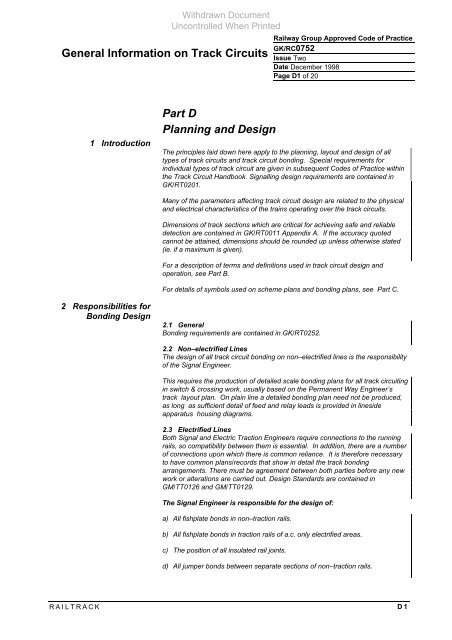
<str<strong>on</strong>g>General</str<strong>on</strong>g> <str<strong>on</strong>g>Informati<strong>on</strong></str<strong>on</strong>g> <strong>on</strong> <strong>Track</strong> <strong>Circuits</strong><br />
1 Introducti<strong>on</strong><br />
2 Resp<strong>on</strong>sibilities for<br />
B<strong>on</strong>ding Design<br />
Withdrawn Document<br />
Unc<strong>on</strong>trolled When Printed<br />
Part D<br />
Planning and Design<br />
Railway Group Approved Code of Practice<br />
GK/RC0752<br />
Issue Two<br />
Date December 1998<br />
Page D1 of 20<br />
The principles laid down here apply to the planning, layout and design of all<br />
types of track circuits and track circuit b<strong>on</strong>ding. Special requirements for<br />
individual types of track circuit are given in subsequent Codes of Practice within<br />
the <strong>Track</strong> Circuit Handbook. Signalling design requirements are c<strong>on</strong>tained in<br />
GK/RT0201.<br />
Many of the parameters affecting track circuit design are related to the physical<br />
and electrical characteristics of the trains operating over the track circuits.<br />
Dimensi<strong>on</strong>s of track secti<strong>on</strong>s which are critical for achieving safe and reliable<br />
detecti<strong>on</strong> are c<strong>on</strong>tained in GK/RT0011 Appendix A. If the accuracy quoted<br />
cannot be attained, dimensi<strong>on</strong>s should be rounded up unless otherwise stated<br />
(ie. if a maximum is given).<br />
For a descripti<strong>on</strong> of terms and definiti<strong>on</strong>s used in track circuit design and<br />
operati<strong>on</strong>, see Part B.<br />
For details of symbols used <strong>on</strong> scheme plans and b<strong>on</strong>ding plans, see Part C.<br />
2.1 <str<strong>on</strong>g>General</str<strong>on</strong>g><br />
B<strong>on</strong>ding requirements are c<strong>on</strong>tained in GK/RT0252.<br />
2.2 N<strong>on</strong>–electrified Lines<br />
The design of all track circuit b<strong>on</strong>ding <strong>on</strong> n<strong>on</strong>–electrified lines is the resp<strong>on</strong>sibility<br />
of the Signal Engineer.<br />
This requires the producti<strong>on</strong> of detailed scale b<strong>on</strong>ding plans for all track circuiting<br />
in switch & crossing work, usually based <strong>on</strong> the Permanent Way Engineer’s<br />
track layout plan. On plain line a detailed b<strong>on</strong>ding plan need not be produced,<br />
as l<strong>on</strong>g as sufficient detail of feed and relay leads is provided in lineside<br />
apparatus housing diagrams.<br />
2.3 Electrified Lines<br />
Both Signal and Electric Tracti<strong>on</strong> Engineers require c<strong>on</strong>necti<strong>on</strong>s to the running<br />
rails, so compatibility between them is essential. In additi<strong>on</strong>, there are a number<br />
of c<strong>on</strong>necti<strong>on</strong>s up<strong>on</strong> which there is comm<strong>on</strong> reliance. It is therefore necessary<br />
to have comm<strong>on</strong> plans/records that show in detail the track b<strong>on</strong>ding<br />
arrangements. There must be agreement between both parties before any new<br />
work or alterati<strong>on</strong>s are carried out. Design Standards are c<strong>on</strong>tained in<br />
GM/TT0126 and GM/TT0129.<br />
The Signal Engineer is resp<strong>on</strong>sible for the design of:<br />
a) All fishplate b<strong>on</strong>ds in n<strong>on</strong>–tracti<strong>on</strong> rails.<br />
b) All fishplate b<strong>on</strong>ds in tracti<strong>on</strong> rails of a.c. <strong>on</strong>ly electrified areas.<br />
c) The positi<strong>on</strong> of all insulated rail joints.<br />
d) All jumper b<strong>on</strong>ds between separate secti<strong>on</strong>s of n<strong>on</strong>–tracti<strong>on</strong> rails.<br />
RAILTRACK D1


