

General Information on Track Circuits - RGS Online
General Information on Track Circuits - RGS Online
General Information on Track Circuits - RGS Online

Create successful ePaper yourself
Turn your PDF publications into a flip-book with our unique Google optimized e-Paper software.
<str<strong>on</strong>g>General</str<strong>on</strong>g> <str<strong>on</strong>g>Informati<strong>on</strong></str<strong>on</strong>g> <strong>on</strong> <strong>Track</strong> <strong>Circuits</strong><br />
12 Mutual Interference<br />
Between <strong>Track</strong><br />
<strong>Circuits</strong><br />
Withdrawn Document<br />
Unc<strong>on</strong>trolled When Printed<br />
Railway Group Approved Code of Practice<br />
GK/RC0752<br />
Issue Two<br />
Date December 1998<br />
Page B17 of 25<br />
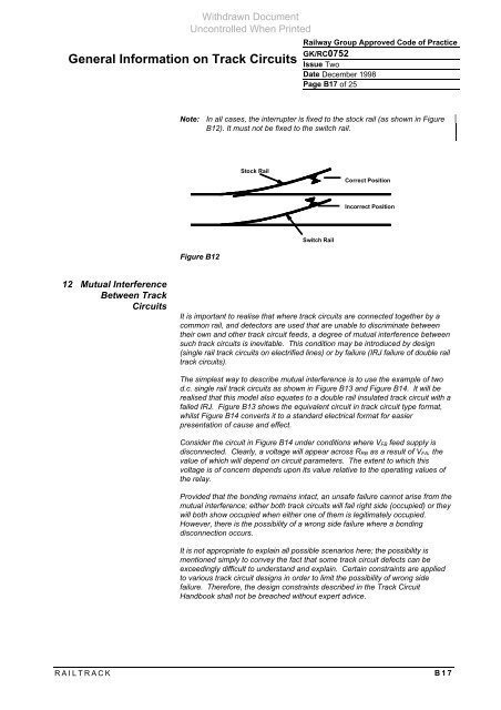
Note: In all cases, the interrupter is fixed to the stock rail (as shown in Figure<br />
B12). It must not be fixed to the switch rail.<br />
Figure B12<br />
Stock Rail<br />
Switch Rail<br />
Correct Positi<strong>on</strong><br />
Incorrect Positi<strong>on</strong><br />
It is important to realise that where track circuits are c<strong>on</strong>nected together by a<br />
comm<strong>on</strong> rail, and detectors are used that are unable to discriminate between<br />
their own and other track circuit feeds, a degree of mutual interference between<br />
such track circuits is inevitable. This c<strong>on</strong>diti<strong>on</strong> may be introduced by design<br />
(single rail track circuits <strong>on</strong> electrified lines) or by failure (IRJ failure of double rail<br />
track circuits).<br />
The simplest way to describe mutual interference is to use the example of two<br />
d.c. single rail track circuits as shown in Figure B13 and Figure B14. It will be<br />
realised that this model also equates to a double rail insulated track circuit with a<br />
failed IRJ. Figure B13 shows the equivalent circuit in track circuit type format,<br />
whilst Figure B14 c<strong>on</strong>verts it to a standard electrical format for easier<br />
presentati<strong>on</strong> of cause and effect.<br />
C<strong>on</strong>sider the circuit in Figure B14 under c<strong>on</strong>diti<strong>on</strong>s where VFB feed supply is<br />
disc<strong>on</strong>nected. Clearly, a voltage will appear across RRB as a result of VFA, the<br />
value of which will depend <strong>on</strong> circuit parameters. The extent to which this<br />
voltage is of c<strong>on</strong>cern depends up<strong>on</strong> its value relative to the operating values of<br />
the relay.<br />
Provided that the b<strong>on</strong>ding remains intact, an unsafe failure cannot arise from the<br />
mutual interference; either both track circuits will fail right side (occupied) or they<br />
will both show occupied when either <strong>on</strong>e of them is legitimately occupied.<br />
However, there is the possibility of a wr<strong>on</strong>g side failure where a b<strong>on</strong>ding<br />
disc<strong>on</strong>necti<strong>on</strong> occurs.<br />
It is not appropriate to explain all possible scenarios here; the possibility is<br />
menti<strong>on</strong>ed simply to c<strong>on</strong>vey the fact that some track circuit defects can be<br />
exceedingly difficult to understand and explain. Certain c<strong>on</strong>straints are applied<br />
to various track circuit designs in order to limit the possibility of wr<strong>on</strong>g side<br />
failure. Therefore, the design c<strong>on</strong>straints described in the <strong>Track</strong> Circuit<br />
Handbook shall not be breached without expert advice.<br />
RAILTRACK B17


