

General Information on Track Circuits - RGS Online
General Information on Track Circuits - RGS Online
General Information on Track Circuits - RGS Online

You also want an ePaper? Increase the reach of your titles
YUMPU automatically turns print PDFs into web optimized ePapers that Google loves.
Withdrawn Document<br />
Unc<strong>on</strong>trolled When Printed<br />
<str<strong>on</strong>g>General</str<strong>on</strong>g> <str<strong>on</strong>g>Informati<strong>on</strong></str<strong>on</strong>g> <strong>on</strong> <strong>Track</strong> <strong>Circuits</strong><br />
Railway Group Approved Code of Practice<br />
GK/RC0752<br />
Issue Two<br />
Date December 1998<br />
Page E35 of 52<br />
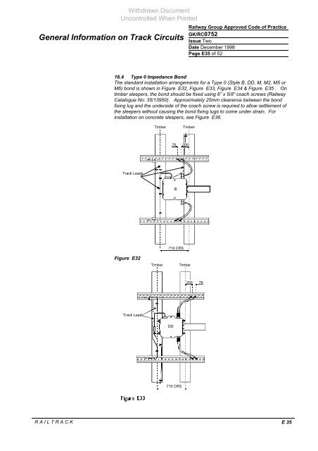
16.4 Type 0 Impedance B<strong>on</strong>d<br />
The standard installati<strong>on</strong> arrangements for a Type 0 (Style B, DD, M, M2, M5 or<br />
M6) b<strong>on</strong>d is shown in Figure E32, Figure E33, Figure E34 & Figure E35 . On<br />
timber sleepers, the b<strong>on</strong>d should be fixed using 6” x 5/8” coach screws (Railway<br />
Catalogue No: 35/13950). Approximately 25mm clearance between the b<strong>on</strong>d<br />
fixing lug and the underside of the coach screw is required to allow settlement of<br />
the sleepers without causing the b<strong>on</strong>d fixing lugs to come under strain. For<br />
installati<strong>on</strong> <strong>on</strong> c<strong>on</strong>crete sleepers, see Figure E36.<br />
<strong>Track</strong> Leads<br />
Figure E32<br />
<strong>Track</strong> Leads<br />
<br />
Timber Timber<br />
710 CRS<br />
R A I L T R A C K E 35<br />
76<br />
B<br />
200<br />
Timber Timber<br />
DD<br />
710 CRS<br />
200<br />
76


