

General Information on Track Circuits - RGS Online
General Information on Track Circuits - RGS Online
General Information on Track Circuits - RGS Online

You also want an ePaper? Increase the reach of your titles
YUMPU automatically turns print PDFs into web optimized ePapers that Google loves.
<str<strong>on</strong>g>General</str<strong>on</strong>g> <str<strong>on</strong>g>Informati<strong>on</strong></str<strong>on</strong>g> <strong>on</strong> <strong>Track</strong> <strong>Circuits</strong><br />
11 Fishplate B<strong>on</strong>ding<br />
Withdrawn Document<br />
Unc<strong>on</strong>trolled When Printed<br />
Railway Group Approved Code of Practice<br />
GK/RC0752<br />
Issue Two<br />
Date December 1998<br />
Page E21 of 52<br />
The method and comp<strong>on</strong>ents described in this secti<strong>on</strong> are to be used to improve<br />
the reliability of the electrical c<strong>on</strong>necti<strong>on</strong> between pieces of rail which are already<br />
in casual electrical c<strong>on</strong>tact by virtue of their c<strong>on</strong>structi<strong>on</strong>.<br />
Whilst the most obvious item in this category is the n<strong>on</strong>–insulated fishplate type<br />
rail joint <strong>on</strong> all n<strong>on</strong>–electrified and a.c. electrified lines, this method of b<strong>on</strong>ding<br />
extends to elements of S & C, such as crossings, wing rails etc, where the<br />
comp<strong>on</strong>ents are also bolted together without intervening insulati<strong>on</strong>.<br />
On d.c. or dual a.c./d.c. electrified lines, it is to be used <strong>on</strong> the signal rail <strong>on</strong>ly of<br />
single rail track circuits. B<strong>on</strong>ding of fishplates in the tracti<strong>on</strong> return rail of d.c.<br />
electrified railways is the resp<strong>on</strong>sibility of the Electric Tracti<strong>on</strong> Engineer.<br />
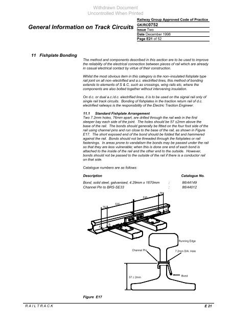
11.1 Standard Fishplate Arrangement<br />
Two 7.2mm holes, 76mm apart, are drilled through the rail web in the first<br />
sleeper bay each side of the joint. The holes should be 57 ±2mm above the<br />
base of the rail. The b<strong>on</strong>ds should generally be fitted <strong>on</strong> the four foot side of the<br />
rail using channel pins and run close to the base of the rail, as shown in Figure<br />
E17. The short exposed end of the b<strong>on</strong>d should be folded flat and hammered<br />
against the rail. B<strong>on</strong>ds should not be threaded through the fishplates or rail<br />
fastenings. In areas pr<strong>on</strong>e to vandalism the b<strong>on</strong>ds may be passed under the rail<br />
so that they are less vulnerable; when this is d<strong>on</strong>e <strong>on</strong>e end of each b<strong>on</strong>d is<br />
attached to the inside of the rail and the other end to the outside. However,<br />
b<strong>on</strong>ds should not be passed to the outside of the rail if there is a c<strong>on</strong>ductor rail<br />
<strong>on</strong> that side.<br />
Catalogue numbers are as follows:<br />
Descripti<strong>on</strong> Catalogue No.<br />
B<strong>on</strong>d, solid steel, galvanised, 4.29mm x 1670mm : 86/44149<br />
Channel Pin to BRS-SE33 : 86/44012<br />
A<br />
Figure E17<br />
76<br />
B<br />
535<br />
57 ± 2mm<br />
R A I L T R A C K E 21<br />
535<br />
A<br />
76<br />
B<br />
Running Edge<br />
Channel Pin 7.2mm DIA. Hole<br />
B<strong>on</strong>d


