

General Information on Track Circuits - RGS Online
General Information on Track Circuits - RGS Online
General Information on Track Circuits - RGS Online

Create successful ePaper yourself
Turn your PDF publications into a flip-book with our unique Google optimized e-Paper software.
<str<strong>on</strong>g>General</str<strong>on</strong>g> <str<strong>on</strong>g>Informati<strong>on</strong></str<strong>on</strong>g> <strong>on</strong> <strong>Track</strong> <strong>Circuits</strong><br />
10 Arrangement of<br />
<strong>Track</strong> Lead Rail<br />
C<strong>on</strong>necti<strong>on</strong>s<br />
(Except Jointless)<br />
A<br />
B<br />
Dis<br />
Box<br />
C<br />
D<br />
Withdrawn Document<br />
Unc<strong>on</strong>trolled When Printed<br />
Railway Group Approved Code of Practice<br />
GK/RC0752<br />
Issue Two<br />
Date December 1998<br />
Page E19 of 52<br />
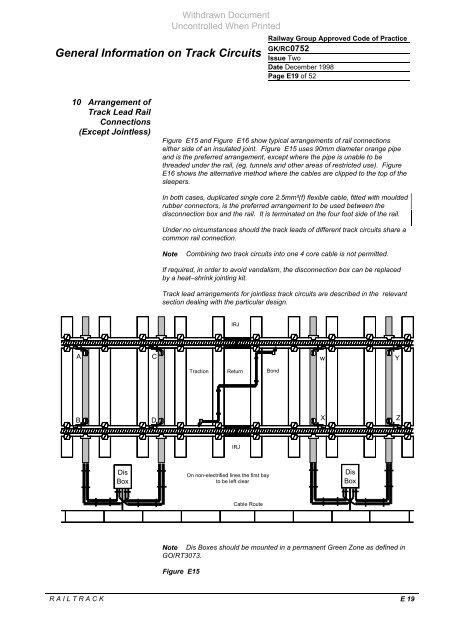
Figure E15 and Figure E16 show typical arrangements of rail c<strong>on</strong>necti<strong>on</strong>s<br />
either side of an insulated joint. Figure E15 uses 90mm diameter orange pipe<br />
and is the preferred arrangement, except where the pipe is unable to be<br />
threaded under the rail, (eg. tunnels and other areas of restricted use). Figure<br />
E16 shows the alternative method where the cables are clipped to the top of the<br />
sleepers.<br />
In both cases, duplicated single core 2.5mm²(f) flexible cable, fitted with moulded<br />
rubber c<strong>on</strong>nectors, is the preferred arrangement to be used between the<br />
disc<strong>on</strong>necti<strong>on</strong> box and the rail. It is terminated <strong>on</strong> the four foot side of the rail.<br />
Under no circumstances should the track leads of different track circuits share a<br />
comm<strong>on</strong> rail c<strong>on</strong>necti<strong>on</strong>.<br />
Note Combining two track circuits into <strong>on</strong>e 4 core cable is not permitted.<br />
If required, in order to avoid vandalism, the disc<strong>on</strong>necti<strong>on</strong> box can be replaced<br />
by a heat–shrink jointing kit.<br />
<strong>Track</strong> lead arrangements for jointless track circuits are described in the relevant<br />
secti<strong>on</strong> dealing with the particular design.<br />
IRJ<br />
Tracti<strong>on</strong> Return B<strong>on</strong>d<br />
w Y<br />
R A I L T R A C K E 19<br />
IRJ<br />
On n<strong>on</strong>-electrified lines the first bay<br />
to be left clear<br />
Cable Route<br />
X<br />
Dis<br />
Box<br />
Note Dis Boxes should be mounted in a permanent Green Z<strong>on</strong>e as defined in<br />
GO/RT3073.<br />
Figure E15<br />
Z


