

General Information on Track Circuits - RGS Online
General Information on Track Circuits - RGS Online
General Information on Track Circuits - RGS Online

You also want an ePaper? Increase the reach of your titles
YUMPU automatically turns print PDFs into web optimized ePapers that Google loves.
Withdrawn Document<br />
Unc<strong>on</strong>trolled When Printed<br />
<str<strong>on</strong>g>General</str<strong>on</strong>g> <str<strong>on</strong>g>Informati<strong>on</strong></str<strong>on</strong>g> <strong>on</strong> <strong>Track</strong> <strong>Circuits</strong><br />
Railway Group Approved Code of Practice<br />
GK/RC0752<br />
Issue Two<br />
Date December 1998<br />
Page F3 of 5<br />
Vibrati<strong>on</strong> causes the clip to wear through the pad, putting the rail in electrical<br />
c<strong>on</strong>tact with the c<strong>on</strong>crete, which degrades the ballast resistance, and, if the<br />
track circuit is d.c. operated, may increase the levels of residual voltage. The<br />
degradati<strong>on</strong> occurs gradually and identificati<strong>on</strong> of the failed insulati<strong>on</strong>s can be<br />
difficult.<br />
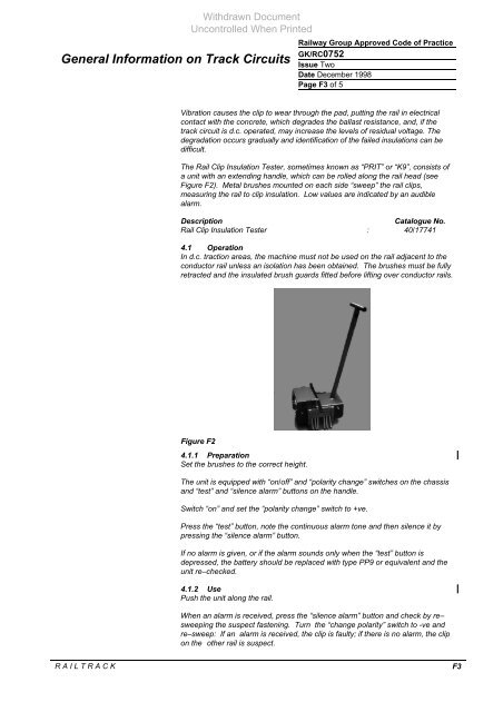
The Rail Clip Insulati<strong>on</strong> Tester, sometimes known as “PRIT” or “K9”, c<strong>on</strong>sists of<br />
a unit with an extending handle, which can be rolled al<strong>on</strong>g the rail head (see<br />
Figure F2). Metal brushes mounted <strong>on</strong> each side “sweep” the rail clips,<br />
measuring the rail to clip insulati<strong>on</strong>. Low values are indicated by an audible<br />
alarm.<br />
Descripti<strong>on</strong> Catalogue No.<br />
Rail Clip Insulati<strong>on</strong> Tester : 40/17741<br />
4.1 Operati<strong>on</strong><br />
In d.c. tracti<strong>on</strong> areas, the machine must not be used <strong>on</strong> the rail adjacent to the<br />
c<strong>on</strong>ductor rail unless an isolati<strong>on</strong> has been obtained. The brushes must be fully<br />
retracted and the insulated brush guards fitted before lifting over c<strong>on</strong>ductor rails.<br />
Figure F2<br />
4.1.1 Preparati<strong>on</strong><br />
Set the brushes to the correct height.<br />
The unit is equipped with “<strong>on</strong>/off” and “polarity change” switches <strong>on</strong> the chassis<br />
and “test” and “silence alarm” butt<strong>on</strong>s <strong>on</strong> the handle.<br />
Switch “<strong>on</strong>” and set the “polarity change” switch to +ve.<br />
Press the “test” butt<strong>on</strong>, note the c<strong>on</strong>tinuous alarm t<strong>on</strong>e and then silence it by<br />
pressing the “silence alarm” butt<strong>on</strong>.<br />
If no alarm is given, or if the alarm sounds <strong>on</strong>ly when the “test” butt<strong>on</strong> is<br />
depressed, the battery should be replaced with type PP9 or equivalent and the<br />
unit re–checked.<br />
4.1.2 Use<br />
Push the unit al<strong>on</strong>g the rail.<br />
When an alarm is received, press the “silence alarm” butt<strong>on</strong> and check by re–<br />
sweeping the suspect fastening. Turn the “change polarity” switch to -ve and<br />
re–sweep: If an alarm is received, the clip is faulty; if there is no alarm, the clip<br />
<strong>on</strong> the other rail is suspect.<br />
R A I L T R A C K F3


