

General Information on Track Circuits - RGS Online
General Information on Track Circuits - RGS Online
General Information on Track Circuits - RGS Online

Create successful ePaper yourself
Turn your PDF publications into a flip-book with our unique Google optimized e-Paper software.
Railway Group Approved Code of Practice<br />
GK/RC0752<br />
Issue Two<br />
Date December 1998<br />
Page D16 of 20<br />
Withdrawn Document<br />
Unc<strong>on</strong>trolled When Printed<br />
<str<strong>on</strong>g>General</str<strong>on</strong>g> <str<strong>on</strong>g>Informati<strong>on</strong></str<strong>on</strong>g> <strong>on</strong> <strong>Track</strong> <strong>Circuits</strong><br />
of the 50Hz system. Immunisati<strong>on</strong> of track circuits <strong>on</strong> the a.c. electrified system<br />
and n<strong>on</strong>-electrified lines against d.c. interference, will usually involve significantly<br />
greater distances (up to 20 km).<br />
The extent of such a z<strong>on</strong>e is dependent up<strong>on</strong> track layout, positi<strong>on</strong> of feeder<br />
stati<strong>on</strong>s and tracti<strong>on</strong> load etc, and requires specialist assessment and<br />
subsequent verificati<strong>on</strong>.<br />
13.12 Buffer Stops<br />
Rail mounted buffer stops in double rail track circuited areas must be fully<br />
insulated. In the case of single rail track circuits in a.c. electrified territory, they<br />
should be insulated from the signal rail.<br />
The type of IRJ provided close to buffer stops must be of a design which offers<br />
similar tensile strength to c<strong>on</strong>venti<strong>on</strong>al steel fishplates (see GK/RT0031).<br />
13.13 Electrical Stagger<br />
Where the electrical energy of <strong>on</strong>e track circuit is capable of operating the<br />
adjacent track circuit due to IRJ failure, the polarity (d.c.) or phase (a.c.) of each<br />
must be arranged so that they oppose rather than reinforce each other. The<br />
intent being that IRJ failure will not result in false operati<strong>on</strong>.<br />
The following methods are available to counteract lack of proper electrical<br />
stagger:<br />
• Provide an additi<strong>on</strong>al transpositi<strong>on</strong> to restore correct electrical stagger.<br />
• Abut feed ends.<br />
• Provide a feed end relay (d.c. track circuits <strong>on</strong>ly).<br />
• C<strong>on</strong>vert <strong>on</strong>e track circuit to a n<strong>on</strong>–interfering form of energy.<br />
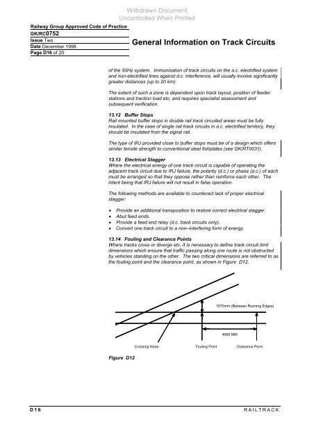
13.14 Fouling and Clearance Points<br />
Where tracks cross or diverge etc, it is necessary to define track circuit limit<br />
dimensi<strong>on</strong>s which ensure that traffic passing al<strong>on</strong>g <strong>on</strong>e route is not obstructed<br />
by vehicles standing <strong>on</strong> the other. The two critical dimensi<strong>on</strong>s are referred to as<br />
the fouling point and the clearance point, as shown in Figure D12.<br />
Figure D12<br />
1970mm (Between Running Edges)<br />
4880 MM<br />
Crossing Nose Fouling Point Clearance Point<br />
D16 RAILTRACK


