

General Information on Track Circuits - RGS Online
General Information on Track Circuits - RGS Online
General Information on Track Circuits - RGS Online

You also want an ePaper? Increase the reach of your titles
YUMPU automatically turns print PDFs into web optimized ePapers that Google loves.
<str<strong>on</strong>g>General</str<strong>on</strong>g> <str<strong>on</strong>g>Informati<strong>on</strong></str<strong>on</strong>g> <strong>on</strong> <strong>Track</strong> <strong>Circuits</strong><br />
Insulati<strong>on</strong><br />
Withdrawn Document<br />
Unc<strong>on</strong>trolled When Printed<br />
C<br />
Railway Group Approved Code of Practice<br />
GK/RC0752<br />
Issue Two<br />
Date December 1998<br />
Page B13 of 25<br />
Insulati<strong>on</strong> Insulati<strong>on</strong><br />
B<br />
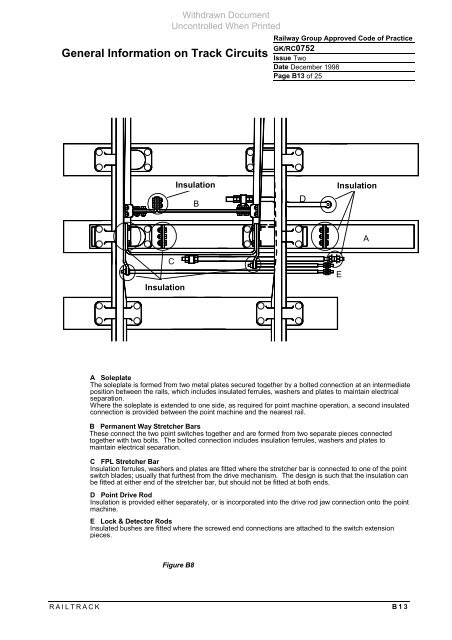
A Soleplate<br />
The soleplate is formed from two metal plates secured together by a bolted c<strong>on</strong>necti<strong>on</strong> at an intermediate<br />
positi<strong>on</strong> between the rails, which includes insulated ferrules, washers and plates to maintain electrical<br />
separati<strong>on</strong>.<br />
Where the soleplate is extended to <strong>on</strong>e side, as required for point machine operati<strong>on</strong>, a sec<strong>on</strong>d insulated<br />
c<strong>on</strong>necti<strong>on</strong> is provided between the point machine and the nearest rail.<br />
B Permanent Way Stretcher Bars<br />
These c<strong>on</strong>nect the two point switches together and are formed from two separate pieces c<strong>on</strong>nected<br />
together with two bolts. The bolted c<strong>on</strong>necti<strong>on</strong> includes insulati<strong>on</strong> ferrules, washers and plates to<br />
maintain electrical separati<strong>on</strong>.<br />
C FPL Stretcher Bar<br />
Insulati<strong>on</strong> ferrules, washers and plates are fitted where the stretcher bar is c<strong>on</strong>nected to <strong>on</strong>e of the point<br />
switch blades; usually that furthest from the drive mechanism. The design is such that the insulati<strong>on</strong> can<br />
be fitted at either end of the stretcher bar, but should not be fitted at both ends.<br />
D Point Drive Rod<br />
Insulati<strong>on</strong> is provided either separately, or is incorporated into the drive rod jaw c<strong>on</strong>necti<strong>on</strong> <strong>on</strong>to the point<br />
machine.<br />
E Lock & Detector Rods<br />
Insulated bushes are fitted where the screwed end c<strong>on</strong>necti<strong>on</strong>s are attached to the switch extensi<strong>on</strong><br />
pieces.<br />
Figure B8<br />
RAILTRACK B13<br />
D<br />
E<br />
A


