

General Information on Track Circuits - RGS Online
General Information on Track Circuits - RGS Online
General Information on Track Circuits - RGS Online

You also want an ePaper? Increase the reach of your titles
YUMPU automatically turns print PDFs into web optimized ePapers that Google loves.
<str<strong>on</strong>g>General</str<strong>on</strong>g> <str<strong>on</strong>g>Informati<strong>on</strong></str<strong>on</strong>g> <strong>on</strong> <strong>Track</strong> <strong>Circuits</strong><br />
5 Cut Secti<strong>on</strong>s<br />
Withdrawn Document<br />
Unc<strong>on</strong>trolled When Printed<br />
Railway Group Approved Code of Practice<br />
GK/RC0752<br />
Issue Two<br />
Date December 1998<br />
Page D5 of 20<br />
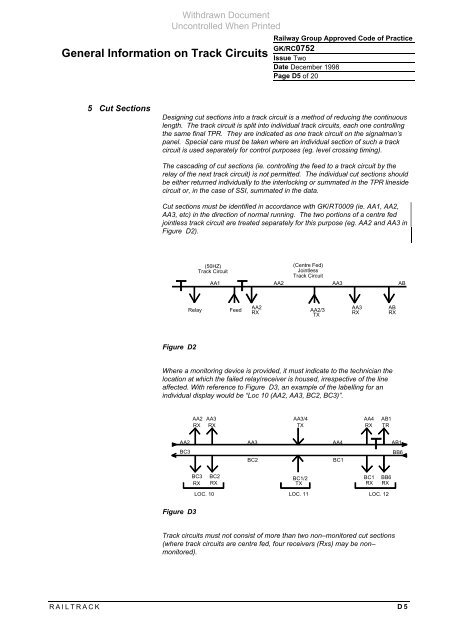
Designing cut secti<strong>on</strong>s into a track circuit is a method of reducing the c<strong>on</strong>tinuous<br />
length. The track circuit is split into individual track circuits, each <strong>on</strong>e c<strong>on</strong>trolling<br />
the same final TPR. They are indicated as <strong>on</strong>e track circuit <strong>on</strong> the signalman’s<br />
panel. Special care must be taken where an individual secti<strong>on</strong> of such a track<br />
circuit is used separately for c<strong>on</strong>trol purposes (eg. level crossing timing).<br />
The cascading of cut secti<strong>on</strong>s (ie. c<strong>on</strong>trolling the feed to a track circuit by the<br />
relay of the next track circuit) is not permitted. The individual cut secti<strong>on</strong>s should<br />
be either returned individually to the interlocking or summated in the TPR lineside<br />
circuit or, in the case of SSI, summated in the data.<br />
Cut secti<strong>on</strong>s must be identified in accordance with GK/RT0009 (ie. AA1, AA2,<br />
AA3, etc) in the directi<strong>on</strong> of normal running. The two porti<strong>on</strong>s of a centre fed<br />
jointless track circuit are treated separately for this purpose (eg. AA2 and AA3 in<br />
Figure D2).<br />
Figure D2<br />
(50HZ)<br />
<strong>Track</strong> Circuit<br />
AA1 AA2 AA3 AB<br />
Relay Feed<br />
(Centre Fed)<br />
Jointless<br />
<strong>Track</strong> Circuit<br />
AA2 AA3 AB<br />
RX<br />
AA2/3<br />
TX<br />
RX RX<br />
Where a m<strong>on</strong>itoring device is provided, it must indicate to the technician the<br />
locati<strong>on</strong> at which the failed relay/receiver is housed, irrespective of the line<br />
affected. With reference to Figure D3, an example of the labelling for an<br />
individual display would be “Loc 10 (AA2, AA3, BC2, BC3)”.<br />
AA2<br />
BC3<br />
Figure D3<br />
AA2 AA3<br />
RX RX<br />
AA3/4<br />
AA4<br />
TX RX<br />
AA3 AA4<br />
BC2 BC1<br />
BC3 BC2<br />
BC1/2<br />
BC1 BB6<br />
RX RX TX<br />
RX RX<br />
LOC. 10 LOC. 11 LOC. 12<br />
<strong>Track</strong> circuits must not c<strong>on</strong>sist of more than two n<strong>on</strong>–m<strong>on</strong>itored cut secti<strong>on</strong>s<br />
(where track circuits are centre fed, four receivers (Rxs) may be n<strong>on</strong>–<br />
m<strong>on</strong>itored).<br />
RAILTRACK D5<br />
AB1<br />
TR<br />
AB1<br />
BB6


