

General Information on Track Circuits - RGS Online
General Information on Track Circuits - RGS Online
General Information on Track Circuits - RGS Online

Create successful ePaper yourself
Turn your PDF publications into a flip-book with our unique Google optimized e-Paper software.
<str<strong>on</strong>g>General</str<strong>on</strong>g> <str<strong>on</strong>g>Informati<strong>on</strong></str<strong>on</strong>g> <strong>on</strong> <strong>Track</strong> <strong>Circuits</strong><br />
16 Impedance B<strong>on</strong>ds<br />
Withdrawn Document<br />
Unc<strong>on</strong>trolled When Printed<br />
Railway Group Approved Code of Practice<br />
GK/RC0752<br />
Issue Two<br />
Date December 1998<br />
Page B23 of 25<br />
16.1 Operati<strong>on</strong><br />
Impedance b<strong>on</strong>ds are devices which allow tracti<strong>on</strong> current (d.c. or a.c.) to pass<br />
through, whilst limiting the track circuit current. They are necessary wherever<br />
double rail tracti<strong>on</strong> return and IRJ dependent track circuits coexist.<br />
An impedance b<strong>on</strong>d is c<strong>on</strong>figured to provide a very low impedance path to<br />
double rail a.c. or d.c. tracti<strong>on</strong> return currents (typically less than 0.4mΩ per coil)<br />
whilst presenting a high enough a.c. impedance between the rails (typically<br />
greater than 15Ω) to allow the operati<strong>on</strong> of track circuits. It also provides a<br />
centre c<strong>on</strong>necti<strong>on</strong> for cross b<strong>on</strong>ding, which minimises the passage of track<br />
circuit current between circuit currents.<br />
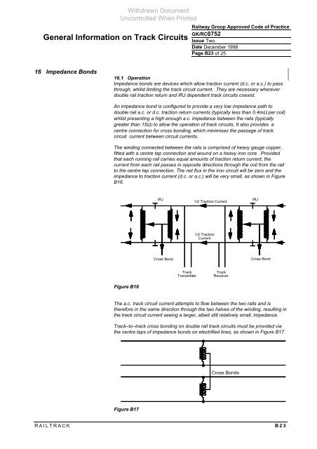
The winding c<strong>on</strong>nected between the rails is comprised of heavy gauge copper,<br />
fitted with a centre tap c<strong>on</strong>necti<strong>on</strong> and wound <strong>on</strong> a heavy ir<strong>on</strong> core. Provided<br />
that each running rail carries equal amounts of tracti<strong>on</strong> return current, the<br />
current from each rail passes in opposite directi<strong>on</strong>s through the coil from the rail<br />
to the centre tap c<strong>on</strong>necti<strong>on</strong>. The net flux in the ir<strong>on</strong> circuit will be zero and the<br />
impedance to tracti<strong>on</strong> current (d.c. or a.c.) will be very small, as shown in Figure<br />
B16.<br />
Figure B16<br />
IRJ IRJ<br />
1/2 Tracti<strong>on</strong> Current<br />
1/2 Tracti<strong>on</strong><br />
Current<br />
Cross B<strong>on</strong>d Cross B<strong>on</strong>d<br />
<strong>Track</strong><br />
Transmitter<br />
<strong>Track</strong><br />
Receiver<br />
The a.c. track circuit current attempts to flow between the two rails and is<br />
therefore in the same directi<strong>on</strong> through the two halves of the winding, resulting in<br />
the track circuit current seeing a larger, albeit still relatively small, impedance.<br />
<strong>Track</strong>–to–track cross b<strong>on</strong>ding <strong>on</strong> double rail track circuits must be provided via<br />
the centre taps of impedance b<strong>on</strong>ds <strong>on</strong> electrified lines, as shown in Figure B17.<br />
Figure B17<br />
Cross B<strong>on</strong>ds<br />
RAILTRACK B23


