

General Information on Track Circuits - RGS Online
General Information on Track Circuits - RGS Online
General Information on Track Circuits - RGS Online

You also want an ePaper? Increase the reach of your titles
YUMPU automatically turns print PDFs into web optimized ePapers that Google loves.
Railway Group Approved Code of Practice<br />
GK/RC0752<br />
Issue Two<br />
Date December 1998<br />
Page E2 of 52<br />
3 <strong>Track</strong> Circuit<br />
Interrupters<br />
Withdrawn Document<br />
Unc<strong>on</strong>trolled When Printed<br />
<str<strong>on</strong>g>General</str<strong>on</strong>g> <str<strong>on</strong>g>Informati<strong>on</strong></str<strong>on</strong>g> <strong>on</strong> <strong>Track</strong> <strong>Circuits</strong><br />
The standard insulated track circuit interrupter assembly is shown <strong>on</strong> drawing<br />
BRS-SM 374, an extract of which is shown in Figure B11.<br />
Catalogue numbers are as follows:<br />
Descripti<strong>on</strong> Catalogue No.<br />
Assembly complete to BRS-SM 374 : 86/44001<br />
Taper pin, BRS-SM 411, 60mm : 86/44011<br />
Body unit to BRS-SM 375 : 86/44003<br />
Insulati<strong>on</strong>s to BRS-SM 376 : 55/27570<br />
Item 1 Insulating bush : 55/25976<br />
Item 2 Insulating washer : 55/28981<br />
Item 3 Channel insulati<strong>on</strong> : 55/27201<br />
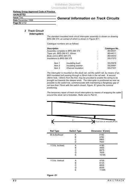
The interrupter is mounted <strong>on</strong> the stock rail, not the switch rail, by means of an<br />
M20 insulated bolt passing through a 28mm hole in the rail web. A sec<strong>on</strong>d<br />
28mm hole, 130mm from the first, may be provided to enable the wiring to be<br />
brought out towards the sleeper ends. The interrupter is positi<strong>on</strong>ed as near as<br />
possible to the switch toe, commensurate with maintaining a flangeway gap of<br />
not less than 70mm with the switch closed. Figure E1 gives the nominal<br />
positi<strong>on</strong>ing.<br />
The temporary repair of track circuit interrupters by means of wrapping the cable<br />
around the stock rail is forbidden. Refer also to Part D.<br />
POSITION OF INTERRUPTER<br />
E 2 R A I L T R A C K<br />
A<br />
Rail Type Switch Type Dimensi<strong>on</strong> 'A'(mm)<br />
95 lb.Bullhead A 4180<br />
B 4780<br />
C 5900<br />
D 7620<br />
113 lb. Inclined A 4180<br />
B 4955<br />
C 6675<br />
D 7635<br />
E 10185<br />
113 lb. Vertical A 4705<br />
B 6125<br />
C 6835<br />
D 8255<br />
E 11095<br />
Figure E1


