

Configuration and Remote System Upgrades in Cyclone IV ... - Altera
Configuration and Remote System Upgrades in Cyclone IV ... - Altera
Configuration and Remote System Upgrades in Cyclone IV ... - Altera

You also want an ePaper? Increase the reach of your titles
YUMPU automatically turns print PDFs into web optimized ePapers that Google loves.
8–28 Chapter 8: <strong>Configuration</strong> <strong>and</strong> <strong>Remote</strong> <strong>System</strong> <strong>Upgrades</strong> <strong>in</strong> <strong>Cyclone</strong> <strong>IV</strong> Devices<br />
<strong>Configuration</strong><br />
The nSTATUS <strong>and</strong> CONF_DONE p<strong>in</strong>s on all target devices are connected together with<br />
external pull-up resistors, as shown <strong>in</strong> Figure 8–8 on page 8–26 <strong>and</strong> Figure 8–9 on<br />
page 8–27. These p<strong>in</strong>s are open-dra<strong>in</strong> bidirectional p<strong>in</strong>s on the devices. When the first<br />
device asserts nCEO (after receiv<strong>in</strong>g all its configuration data), it releases its CONF_DONE<br />
p<strong>in</strong>. However, the subsequent devices <strong>in</strong> the cha<strong>in</strong> keep this shared CONF_DONE l<strong>in</strong>e<br />
low until they receive their configuration data. When all target devices <strong>in</strong> the cha<strong>in</strong><br />
receive their configuration data <strong>and</strong> release CONF_DONE, the pull-up resistor drives a<br />
high level on this l<strong>in</strong>e <strong>and</strong> all devices simultaneously enter <strong>in</strong>itialization mode.<br />
Guidel<strong>in</strong>es for Connect<strong>in</strong>g Parallel Flash to <strong>Cyclone</strong> <strong>IV</strong> E Devices for an AP<br />
Interface<br />
For s<strong>in</strong>gle- <strong>and</strong> multi-device AP configuration, the board trace length <strong>and</strong> load<strong>in</strong>g<br />
between the supported parallel flash <strong>and</strong> <strong>Cyclone</strong> <strong>IV</strong> E devices must follow the<br />
recommendations listed <strong>in</strong> Table 8–10. These recommendations also apply to an AP<br />
configuration with multiple bus masters.<br />
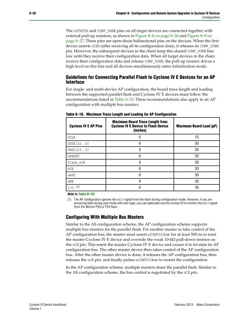
Table 8–10. Maximum Trace Length <strong>and</strong> Load<strong>in</strong>g for AP <strong>Configuration</strong><br />
<strong>Cyclone</strong> <strong>IV</strong> E AP P<strong>in</strong>s<br />
Maximum Board Trace Length from<br />
<strong>Cyclone</strong> <strong>IV</strong> E Device to Flash Device<br />
(<strong>in</strong>ches)<br />
Configur<strong>in</strong>g With Multiple Bus Masters<br />
Maximum Board Load (pF)<br />
DCLK 6 15<br />
DATA[15..0] 6 30<br />
PADD[23..0] 6 30<br />
nRESET 6 30<br />
Flash_nCE 6 30<br />
nOE 6 30<br />
nAVD 6 30<br />
nWE 6 30<br />
I/O (1) 6 30<br />
Note to Table 8–10:<br />
(1) The AP configuration ignores the WAIT signal from the flash dur<strong>in</strong>g configuration mode. However, if you are<br />
access<strong>in</strong>g flash dur<strong>in</strong>g user mode with user logic, you can optionally use the normal I/O to monitor the WAIT signal<br />
from the Micron P30 or P33 flash.<br />
Similar to the AS configuration scheme, the AP configuration scheme supports<br />
multiple bus masters for the parallel flash. For another master to take control of the<br />
AP configuration bus, the master must assert nCONFIG low for at least 500 ns to reset<br />
the master <strong>Cyclone</strong> <strong>IV</strong> E device <strong>and</strong> override the weak 10-k pull-down resistor on<br />
the nCE p<strong>in</strong>. This resets the master <strong>Cyclone</strong> <strong>IV</strong> E device <strong>and</strong> causes it to tri-state its AP<br />
configuration bus. The other master device then takes control of the AP configuration<br />
bus. After the other master device is done, it releases the AP configuration bus, then<br />
releases the nCE p<strong>in</strong>, <strong>and</strong> f<strong>in</strong>ally pulses nCONFIG low to restart the configuration.<br />
In the AP configuration scheme, multiple masters share the parallel flash. Similar to<br />
the AS configuration scheme, the bus control is negotiated by the nCE p<strong>in</strong>.<br />
<strong>Cyclone</strong> <strong>IV</strong> Device H<strong>and</strong>book, February 2013 <strong>Altera</strong> Corporation<br />
Volume 1


