

Configuration and Remote System Upgrades in Cyclone IV ... - Altera
Configuration and Remote System Upgrades in Cyclone IV ... - Altera
Configuration and Remote System Upgrades in Cyclone IV ... - Altera

You also want an ePaper? Increase the reach of your titles
YUMPU automatically turns print PDFs into web optimized ePapers that Google loves.
Chapter 8: <strong>Configuration</strong> <strong>and</strong> <strong>Remote</strong> <strong>System</strong> <strong>Upgrades</strong> <strong>in</strong> <strong>Cyclone</strong> <strong>IV</strong> Devices 8–41<br />
<strong>Configuration</strong><br />
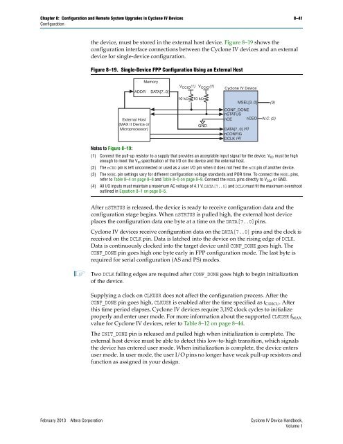
the device, must be stored <strong>in</strong> the external host device. Figure 8–19 shows the<br />
configuration <strong>in</strong>terface connections between the <strong>Cyclone</strong> <strong>IV</strong> devices <strong>and</strong> an external<br />
device for s<strong>in</strong>gle-device configuration.<br />
Figure 8–19. S<strong>in</strong>gle-Device FPP <strong>Configuration</strong> Us<strong>in</strong>g an External Host<br />
Notes to Figure 8–19:<br />
ADDR<br />
External Host<br />
(MAX II Device or<br />
Microprocessor)<br />
Memory<br />
DATA[7..0]<br />
V CCIO (1) V CCIO (1)<br />
<strong>Cyclone</strong> <strong>IV</strong> Device<br />
CONF_DONE<br />
nSTATUS<br />
nCE nCEO<br />
(1) Connect the pull-up resistor to a supply that provides an acceptable <strong>in</strong>put signal for the device. VCC must be high<br />
enough to meet the VIH specification of the I/O on the device <strong>and</strong> the external host.<br />
(2) The nCEO p<strong>in</strong> is left unconnected or used as a user I/O p<strong>in</strong> when it does not feed the nCE p<strong>in</strong> of another device.<br />
(3) The MSEL p<strong>in</strong> sett<strong>in</strong>gs vary for different configuration voltage st<strong>and</strong>ards <strong>and</strong> POR time. To connect the MSEL p<strong>in</strong>s,<br />
refer to Table 8–4 on page 8–8 <strong>and</strong> Table 8–5 on page 8–9. Connect the MSEL p<strong>in</strong>s directly to VCCA or GND.<br />
(4) All I/O <strong>in</strong>puts must ma<strong>in</strong>ta<strong>in</strong> a maximum AC voltage of 4.1 V. DATA[7..0] <strong>and</strong> DCLK must fit the maximum overshoot<br />
outl<strong>in</strong>ed <strong>in</strong> Equation 8–1 on page 8–5.<br />
After nSTATUS is released, the device is ready to receive configuration data <strong>and</strong> the<br />
configuration stage beg<strong>in</strong>s. When nSTATUS is pulled high, the external host device<br />
places the configuration data one byte at a time on the DATA[7..0]p<strong>in</strong>s.<br />
<strong>Cyclone</strong> <strong>IV</strong> devices receive configuration data on the DATA[7..0] p<strong>in</strong>s <strong>and</strong> the clock is<br />
received on the DCLK p<strong>in</strong>. Data is latched <strong>in</strong>to the device on the ris<strong>in</strong>g edge of DCLK.<br />
Data is cont<strong>in</strong>uously clocked <strong>in</strong>to the target device until CONF_DONE goes high. The<br />
CONF_DONE p<strong>in</strong> goes high one byte early <strong>in</strong> FPP configuration mode. The last byte is<br />
required for serial configuration (AS <strong>and</strong> PS) modes.<br />
1 Two DCLK fall<strong>in</strong>g edges are required after CONF_DONE goes high to beg<strong>in</strong> <strong>in</strong>itialization<br />
of the device.<br />
Supply<strong>in</strong>g a clock on CLKUSR does not affect the configuration process. After the<br />
CONF_DONE p<strong>in</strong> goes high, CLKUSR is enabled after the time specified as t CD2CU. After<br />
this time period elapses, <strong>Cyclone</strong> <strong>IV</strong> devices require 3,192 clock cycles to <strong>in</strong>itialize<br />
properly <strong>and</strong> enter user mode. For more <strong>in</strong>formation about the supported CLKUSR f MAX<br />
value for <strong>Cyclone</strong> <strong>IV</strong> devices, refer to Table 8–12 on page 8–44.<br />
The INIT_DONE p<strong>in</strong> is released <strong>and</strong> pulled high when <strong>in</strong>itialization is complete. The<br />
external host device must be able to detect this low-to-high transition, which signals<br />
the device has entered user mode. When <strong>in</strong>itialization is complete, the device enters<br />
user mode. In user mode, the user I/O p<strong>in</strong>s no longer have weak pull-up resistors <strong>and</strong><br />
function as assigned <strong>in</strong> your design.<br />
February 2013 <strong>Altera</strong> Corporation <strong>Cyclone</strong> <strong>IV</strong> Device H<strong>and</strong>book,<br />
Volume 1<br />
10 k<br />
10 k<br />
GND<br />
MSEL[3..0]<br />
DATA[7..0] (4)<br />
nCONFIG<br />
DCLK (4)<br />
(3)<br />
N.C. (2)


