

Configuration and Remote System Upgrades in Cyclone IV ... - Altera
Configuration and Remote System Upgrades in Cyclone IV ... - Altera
Configuration and Remote System Upgrades in Cyclone IV ... - Altera

Create successful ePaper yourself
Turn your PDF publications into a flip-book with our unique Google optimized e-Paper software.
Chapter 8: <strong>Configuration</strong> <strong>and</strong> <strong>Remote</strong> <strong>System</strong> <strong>Upgrades</strong> <strong>in</strong> <strong>Cyclone</strong> <strong>IV</strong> Devices 8–29<br />
<strong>Configuration</strong><br />
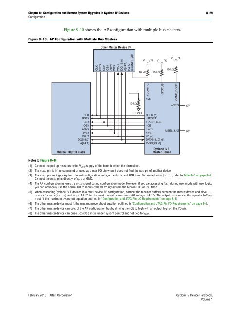
Figure 8–10 shows the AP configuration with multiple bus masters.<br />
Figure 8–10. AP <strong>Configuration</strong> with Multiple Bus Masters<br />
Notes to Figure 8–10:<br />
CLK<br />
RST#<br />
CE#<br />
OE#<br />
ADV#<br />
WE#<br />
WAIT<br />
DQ[15:0]<br />
A[24:1]<br />
Micron P30/P33 Flash<br />
Other Master Device (6)<br />
CLK<br />
RST#<br />
CE#<br />
OE#<br />
ADV#<br />
WE#<br />
WAIT<br />
DQ[15:0]<br />
A[24:1]<br />
I/O (7)<br />
nCONFIG (8)<br />
DCLK (5)<br />
nRESET<br />
FLASH_nCE<br />
nOE<br />
nAVD<br />
MSEL[3..0]<br />
nWE<br />
I/O (4)<br />
DATA[15..0] (5)<br />
PADD[23..0]<br />
(1) Connect the pull-up resistors to the VCCIO supply of the bank <strong>in</strong> which the p<strong>in</strong> resides.<br />
(2) The nCEO p<strong>in</strong> is left unconnected or used as a user I/O p<strong>in</strong> when it does not feed the nCE p<strong>in</strong> of another device.<br />
(3) The MSEL p<strong>in</strong> sett<strong>in</strong>gs vary for different configuration voltage st<strong>and</strong>ards <strong>and</strong> POR time. To connect MSEL[3..0], refer to Table 8–5 on page 8–9.<br />
Connect the MSEL p<strong>in</strong>s directly to VCCA or GND.<br />
(4) The AP configuration ignores the WAIT signal dur<strong>in</strong>g configuration mode. However, if you are access<strong>in</strong>g flash dur<strong>in</strong>g user mode with user logic,<br />
you can optionally use the normal I/O to monitor the WAIT signal from the Micron P30 or P33 flash.<br />
(5) When cascad<strong>in</strong>g <strong>Cyclone</strong> <strong>IV</strong> E devices <strong>in</strong> a multi-device AP configuration, connect the repeater buffers between the master device <strong>and</strong> slave<br />
devices for DATA[15..0] <strong>and</strong> DCLK. All I/O <strong>in</strong>puts must ma<strong>in</strong>ta<strong>in</strong> a maximum AC voltage of 4.1 V. The output resistance of the repeater buffers<br />
must fit the maximum overshoot equation outl<strong>in</strong>ed <strong>in</strong> “<strong>Configuration</strong> <strong>and</strong> JTAG P<strong>in</strong> I/O Requirements” on page 8–5.<br />
(6) The other master device must fit the maximum overshoot equation outl<strong>in</strong>ed <strong>in</strong> “<strong>Configuration</strong> <strong>and</strong> JTAG P<strong>in</strong> I/O Requirements” on page 8–5.<br />
(7) The other master device can control the AP configuration bus by driv<strong>in</strong>g the nCE to high with an output high on the I/O p<strong>in</strong>.<br />
(8) The other master device can pulse nCONFIG if it is under system control <strong>and</strong> not tied to VCCIO. February 2013 <strong>Altera</strong> Corporation <strong>Cyclone</strong> <strong>IV</strong> Device H<strong>and</strong>book,<br />
Volume 1<br />
10 k<br />
10 k<br />
GND<br />
V CCIO (1)<br />
nCONFIG<br />
nCE<br />
10 k<br />
V CCIO (1)<br />
nSTATUS<br />
10 k<br />
<strong>Cyclone</strong> <strong>IV</strong> E<br />
Master Device<br />
V CCIO (1)<br />
CONF_DONE<br />
nCEO<br />
(2)<br />
(3)


