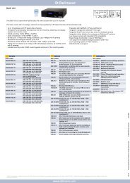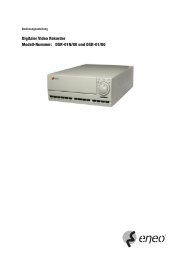
Digital Video Recorder, H.264 Models: DMR-5008/500 (8-Channel ...
Digital Video Recorder, H.264 Models: DMR-5008/500 (8-Channel ...
Digital Video Recorder, H.264 Models: DMR-5008/500 (8-Channel ...

You also want an ePaper? Increase the reach of your titles
YUMPU automatically turns print PDFs into web optimized ePapers that Google loves.
4<br />
User’s Manual<br />
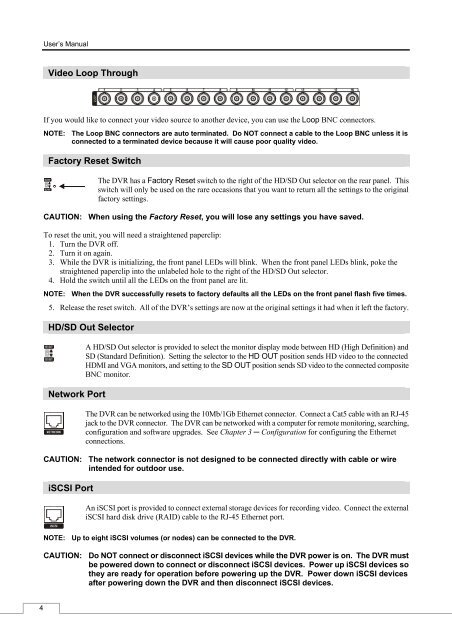
<strong>Video</strong> Loop Through<br />
If you would like to connect your video source to another device, you can use the Loop BNC connectors.<br />
NOTE: The Loop BNC connectors are auto terminated. Do NOT connect a cable to the Loop BNC unless it is<br />
connected to a terminated device because it will cause poor quality video.<br />
Factory Reset Switch<br />
The DVR has a Factory Reset switch to the right of the HD/SD Out selector on the rear panel. This<br />
switch will only be used on the rare occasions that you want to return all the settings to the original<br />
factory settings.<br />
CAUTION: When using the Factory Reset, you will lose any settings you have saved.<br />
To reset the unit, you will need a straightened paperclip:<br />
1. Turn the DVR off.<br />
2. Turn it on again.<br />
3. While the DVR is initializing, the front panel LEDs will blink. When the front panel LEDs blink, poke the<br />
straightened paperclip into the unlabeled hole to the right of the HD/SD Out selector.<br />
4. Hold the switch until all the LEDs on the front panel are lit.<br />
NOTE: When the DVR successfully resets to factory defaults all the LEDs on the front panel flash five times.<br />
5. Release the reset switch. All of the DVR’s settings are now at the original settings it had when it left the factory.<br />
HD/SD Out Selector<br />
Network Port<br />
A HD/SD Out selector is provided to select the monitor display mode between HD (High Definition) and<br />
SD (Standard Definition). Setting the selector to the HD OUT position sends HD video to the connected<br />
HDMI and VGA monitors, and setting to the SD OUT position sends SD video to the connected composite<br />
BNC monitor.<br />
The DVR can be networked using the 10Mb/1Gb Ethernet connector. Connect a Cat5 cable with an RJ-45<br />
jack to the DVR connector. The DVR can be networked with a computer for remote monitoring, searching,<br />
configuration and software upgrades. See Chapter 3 ─ Configuration for configuring the Ethernet<br />
connections.<br />
CAUTION: The network connector is not designed to be connected directly with cable or wire<br />
intended for outdoor use.<br />
iSCSI Port<br />
An iSCSI port is provided to connect external storage devices for recording video. Connect the external<br />
iSCSI hard disk drive (RAID) cable to the RJ-45 Ethernet port.<br />
NOTE: Up to eight iSCSI volumes (or nodes) can be connected to the DVR.<br />
CAUTION: Do NOT connect or disconnect iSCSI devices while the DVR power is on. The DVR must<br />
be powered down to connect or disconnect iSCSI devices. Power up iSCSI devices so<br />
they are ready for operation before powering up the DVR. Power down iSCSI devices<br />
after powering down the DVR and then disconnect iSCSI devices.