

Operation and Maintenance Manual for
Operation and Maintenance Manual for
Operation and Maintenance Manual for

You also want an ePaper? Increase the reach of your titles
YUMPU automatically turns print PDFs into web optimized ePapers that Google loves.
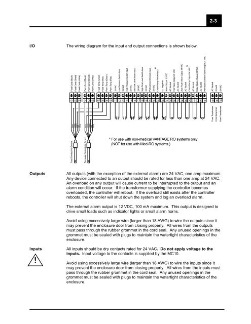
I/O The wiring diagram <strong>for</strong> the input <strong>and</strong> output connections is shown below.<br />
Feed Cond (Black)<br />
Feed Conductivity Sensor<br />
Feed Cond (Shield)<br />
Feed Cond (White)<br />
Black<br />
Green<br />
Shield<br />
Red<br />
White<br />
Perm Cond (Black)<br />
Permeate Conductivity Sensor<br />
Perm Cond (Shield)<br />
Perm Cond (White)<br />
Black<br />
Green<br />
Shield<br />
Red<br />
White<br />
Feed Temp (Green)<br />
Feed Temp (Red)<br />
Perm Temp (Green)<br />
Perm Temp (Red)<br />
24 VAC<br />
Low Pressure Switch Input<br />
24 VAC<br />
High Pressure Switch Input<br />
24 VAC<br />
Mid Tank Level Switch Input<br />
24 VAC<br />
High Tank Level Switch Input<br />
24 VAC<br />
Pretreatment Interlock Input<br />
24 VAC<br />
Chem Pump Failure Input *<br />
Outputs All outputs (with the exception of the external alarm) are 24 VAC, one amp maximum.<br />
Any device connected to an output should be rated <strong>for</strong> less than one amp at 24 VAC.<br />
An overload on any output will cause current to be interrupted to the output <strong>and</strong> an<br />
alarm condition will occur. If the trans<strong>for</strong>mer supplying the controller becomes<br />
overloaded, the controller will reboot. If the overload still exists after the controller<br />
reboots, the controller will shut down the system <strong>and</strong> log an overload alarm.<br />
The external alarm output is 12 VDC, 100 mA maximum. This output is designed to<br />
drive small loads such as indicator lights or small alarm horns.<br />
Avoid using excessively large wire (larger than 18 AWG) to wire the outputs since it<br />
may prevent the enclosure door from closing properly. All wires from the outputs<br />
must pass through the rubber grommet in the cord seal. Any unused openings in the<br />
grommet must be sealed with plugs to maintain the watertight characteristics of the<br />
enclosure.<br />
Inputs All inputs should be dry contacts rated <strong>for</strong> 24 VAC. Do not apply voltage to the<br />
inputs. Input voltage to the contacts is supplied by the MC10.<br />
!<br />
Avoid using excessively large wire (larger than 18 AWG) to wire the inputs since it<br />
may prevent the enclosure door from closing properly. All wires from the inputs must<br />
pass through the rubber grommet in the cord seal. Any unused openings in the<br />
grommet must be sealed with plugs to maintain the watertight characteristics of the<br />
enclosure.<br />
DC Negative<br />
Alarm Output 12 VDC<br />
AC Neutral<br />
Inlet Valve Output 24 VAC<br />
AC Neutral<br />
Auto Flush Valve Output 24 VAC<br />
AC Neutral<br />
Chem Pump Output 24 VAC *<br />
AC Neutral<br />
Motor Starter Output 24 VAC<br />
AC Neutral<br />
Permeate Diversion Valve Output 24 VAC<br />
01 02 03 04 05 06 07 08 09 10 11 12 13 14 15 16 17 18 19 20 21 22 23 24 25 26 27 28 29 30 31 32 33 34 35 36 37<br />
* For use with non-medical VANTAGE RO systems only.<br />
(NOT <strong>for</strong> use with Med-RO systems.)<br />
2-3<br />
AC Neutral<br />
From Trans<strong>for</strong>mer<br />
Ground<br />
From Backpanel<br />
24 VAC<br />
From Trans<strong>for</strong>mer


