

Operation and Maintenance Manual for
Operation and Maintenance Manual for
Operation and Maintenance Manual for

Create successful ePaper yourself
Turn your PDF publications into a flip-book with our unique Google optimized e-Paper software.
<strong>and</strong> seconds), date (day, date, month <strong>and</strong> year) access (factory default access code<br />
= 12345) <strong>and</strong> sanitize lockout (factory default sanitize lockout code = 12345) codes.<br />
The MC10 maintains time on a 24 hour clock (i.e., military style). The hours,<br />
minutes, <strong>and</strong> seconds are changed on separate screens by entering the appropriate<br />
number <strong>and</strong> pressing “ENTER”. Date, month, <strong>and</strong> year are entered in the same<br />
fashion. The MC10 also requires that the day of the week be entered (Sunday = 1,<br />
Saturday = 7).<br />
The second selection from the Settings Screen, number 1 key, allows the user to<br />
change the operating mode of the MC10; Sanitize, St<strong>and</strong>by or Tank/Direct Feed<br />
modes. The third selection, number 2 key, allows access to the Settings data entry<br />
screens. The user is prompted <strong>for</strong> the access code to enter sub menu 0 (Clock) or 2<br />
(Settings) of the Settings screen (factory default access code = 12345).<br />
The fourth selection, number 3 key, automatically initializes the modem. This only<br />
needs to be done one time after a modem is installed in the controller. The fifth<br />
selection, number 4 key, allows the user to select the data log interval. The sixth<br />
selection, number 5 key, erases the data currently in the data logger.<br />
Upon entering the Settings data entry screens (by pressing “2” from the main<br />
Settings screen), the user will have the option of entering an index number <strong>for</strong> a<br />
particular setting. This enables the user to go directly to a particular setting without<br />
scrolling through the entire list of settings. Alternatively, the user may scroll through<br />
the settings with the up <strong>and</strong> down arrow keys.<br />
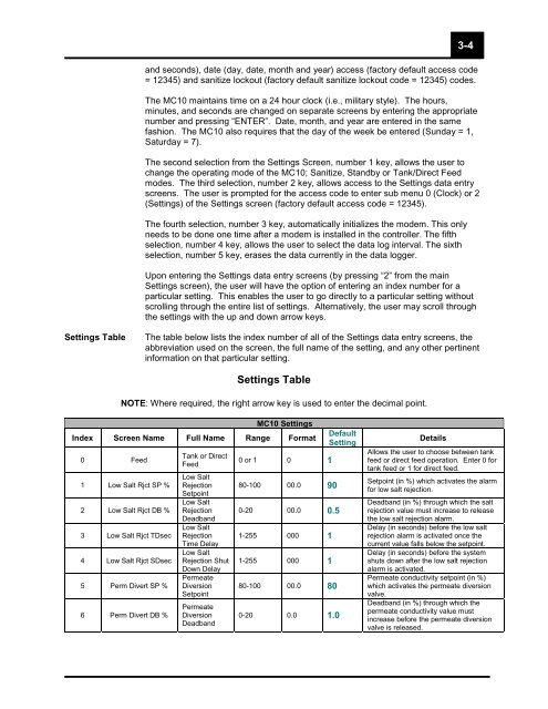
Settings Table The table below lists the index number of all of the Settings data entry screens, the<br />
abbreviation used on the screen, the full name of the setting, <strong>and</strong> any other pertinent<br />
in<strong>for</strong>mation on that particular setting.<br />
Settings Table<br />
NOTE: Where required, the right arrow key is used to enter the decimal point.<br />
MC10 Settings<br />
Index Screen Name Full Name Range Format<br />
0 Feed<br />
1 Low Salt Rjct SP %<br />
2 Low Salt Rjct DB %<br />
3 Low Salt Rjct TDsec<br />
4 Low Salt Rjct SDsec<br />
5 Perm Divert SP %<br />
6 Perm Divert DB %<br />
Tank or Direct<br />
Feed<br />
Low Salt<br />
Rejection<br />
Setpoint<br />
Low Salt<br />
Rejection<br />
Deadb<strong>and</strong><br />
Low Salt<br />
Rejection<br />
Time Delay<br />
Low Salt<br />
Rejection Shut<br />
Down Delay<br />
Permeate<br />
Diversion<br />
Setpoint<br />
Permeate<br />
Diversion<br />
Deadb<strong>and</strong><br />
0 or 1 0 1<br />
80-100 00.0 90<br />
0-20 00.0 0.5<br />
1-255 000 1<br />
1-255 000 1<br />
80-100 00.0 80<br />
0-20 0.0 1.0<br />
Default<br />
Setting<br />
Details<br />
Allows the user to choose between tank<br />
feed or direct feed operation. Enter 0 <strong>for</strong><br />
tank feed or 1 <strong>for</strong> direct feed.<br />
Setpoint (in %) which activates the alarm<br />
<strong>for</strong> low salt rejection.<br />
Deadb<strong>and</strong> (in %) through which the salt<br />
rejection value must increase to release<br />
the low salt rejection alarm.<br />
Delay (in seconds) be<strong>for</strong>e the low salt<br />
rejection alarm is activated once the<br />
current value falls below the setpoint.<br />
Delay (in seconds) be<strong>for</strong>e the system<br />
shuts down after the low salt rejection<br />
alarm is activated.<br />
Permeate conductivity setpoint (in %)<br />
which activates the permeate diversion<br />
valve.<br />
3-4<br />
Deadb<strong>and</strong> (in %) through which the<br />
permeate conductivity value must<br />
increase be<strong>for</strong>e the permeate diversion<br />
valve is released.


