

Proceedings of the European Summer School of Photovoltaics 4 â 7 ...
Proceedings of the European Summer School of Photovoltaics 4 â 7 ...
Proceedings of the European Summer School of Photovoltaics 4 â 7 ...

You also want an ePaper? Increase the reach of your titles
YUMPU automatically turns print PDFs into web optimized ePapers that Google loves.
Organic photovoltaics – chosen aspects<br />
Justyna Szostak, Ryszard Signerski, Kamila Żelechowska, Jan Godlewski<br />
Gdańsk University <strong>of</strong> Technology, Department <strong>of</strong> Physics <strong>of</strong> Electronic Phenomena, Faculty <strong>of</strong> Applied Physics and Ma<strong>the</strong>matics<br />
Preparation <strong>of</strong> inorganic solar cells usually requires very costly<br />
and complicated high temperature vacuum deposition techniques.<br />
Fur<strong>the</strong>rmore, materials used for fabrication <strong>of</strong> <strong>the</strong>se cells are<br />
expensive and <strong>of</strong>ten dangerous for <strong>the</strong> environment, not to mention<br />
<strong>the</strong> hazardous and toxic substances used during manufacturing<br />
process and its by-products [1]. Hence, organic solar cells<br />
(OSCs), that can be fabricated from relatively cheap materials,<br />
using simple solution coating techniques, i.e. ink-jet printing or<br />
spin and dip coating, which do not require high temperatures nor<br />
<strong>the</strong> usage <strong>of</strong> hazardous substances, seem to be a promising alternative<br />
for <strong>the</strong> inorganic photovoltaics. Moreover, <strong>the</strong> number<br />
<strong>of</strong> organic materials is much greater than <strong>the</strong> number <strong>of</strong> inorganic<br />
ones, so <strong>the</strong> potential <strong>of</strong> applications <strong>of</strong> organic materials in<br />
photovoltaics is greater as well. However, relatively low efficiency<br />
and fast degradation <strong>of</strong> organic solar cells [2, 3] are serious drawbacks<br />
that hinder commercialization <strong>of</strong> organic photovoltaic diodes.<br />
Designing organic solar cells with higher energy conversion<br />
efficiency and stability is impossible without extensive knowledge<br />
on all physical and chemical processes taking place inside organic<br />
photovoltaic devices in <strong>the</strong> dark and under illumination. Even<br />
though <strong>the</strong>re are many experimental works showing <strong>the</strong> performance<br />
<strong>of</strong> OSCs, <strong>the</strong>oretical model for <strong>the</strong> photovoltaic effect taking<br />
place in <strong>the</strong>se devices has not been developed yet. Significant<br />
differences in structure <strong>of</strong> organic and inorganic materials<br />
result in different types <strong>of</strong> interactions between molecules. Thus,<br />
even though <strong>the</strong> mechanisms <strong>of</strong> photovoltaic effect in inorganic<br />
systems are well known and described in literature, processes<br />
that affect photovoltaic phenomenon in organic systems still need<br />
fur<strong>the</strong>r understanding. Thus, research we run in our laboratory is<br />
focused on analysis <strong>of</strong> <strong>the</strong> above mentioned processes.<br />
Photovoltaic phenomenon in organic systems<br />
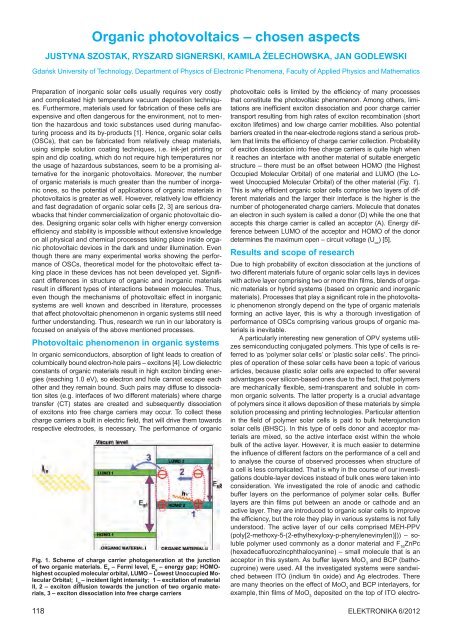
In organic semiconductors, absorption <strong>of</strong> light leads to creation <strong>of</strong><br />
columbically bound electron-hole pairs – excitons [4]. Low dielectric<br />
constants <strong>of</strong> organic materials result in high exciton binding energies<br />
(reaching 1.0 eV), so electron and hole cannot escape each<br />
o<strong>the</strong>r and <strong>the</strong>y remain bound. Such pairs may diffuse to dissociation<br />
sites (e.g. interfaces <strong>of</strong> two different materials) where charge<br />
transfer (CT) states are created and subsequently dissociation<br />
<strong>of</strong> excitons into free charge carriers may occur. To collect <strong>the</strong>se<br />
charge carriers a built in electric field, that will drive <strong>the</strong>m towards<br />
respective electrodes, is necessary. The performance <strong>of</strong> organic<br />
Fig. 1. Scheme <strong>of</strong> charge carrier photogeneration at <strong>the</strong> junction<br />
<strong>of</strong> two organic materials. E F<br />
– Fermi level, E g<br />
– energy gap; HOMOhighest<br />
occupied molecular orbital, LUMO – Lowest Unoccupied Molecular<br />
Orbital; I in<br />
– incident light intensity; 1 – excitation <strong>of</strong> material<br />
II, 2 – exciton diffusion towards <strong>the</strong> junction <strong>of</strong> two organic materials,<br />
3 – exciton dissociation into free charge carriers<br />
118<br />
photovoltaic cells is limited by <strong>the</strong> efficiency <strong>of</strong> many processes<br />
that constitute <strong>the</strong> photovoltaic phenomenon. Among o<strong>the</strong>rs, limitations<br />
are inefficient exciton dissociation and poor charge carrier<br />
transport resulting from high rates <strong>of</strong> exciton recombination (short<br />
exciton lifetimes) and low charge carrier mobilities. Also potential<br />
barriers created in <strong>the</strong> near-electrode regions stand a serious problem<br />
that limits <strong>the</strong> efficiency <strong>of</strong> charge carrier collection. Probability<br />
<strong>of</strong> exciton dissociation into free charge carriers is quite high when<br />
it reaches an interface with ano<strong>the</strong>r material <strong>of</strong> suitable energetic<br />
structure – <strong>the</strong>re must be an <strong>of</strong>fset between HOMO (<strong>the</strong> Highest<br />
Occupied Molecular Orbital) <strong>of</strong> one material and LUMO (<strong>the</strong> Lowest<br />
Unoccupied Molecular Orbital) <strong>of</strong> <strong>the</strong> o<strong>the</strong>r material (Fig. 1).<br />
This is why efficient organic solar cells comprise two layers <strong>of</strong> different<br />
materials and <strong>the</strong> larger <strong>the</strong>ir interface is <strong>the</strong> higher is <strong>the</strong><br />
number <strong>of</strong> photogenerated charge carriers. Molecule that donates<br />
an electron in such system is called a donor (D) while <strong>the</strong> one that<br />
accepts this charge carrier is called an acceptor (A). Energy difference<br />
between LUMO <strong>of</strong> <strong>the</strong> acceptor and HOMO <strong>of</strong> <strong>the</strong> donor<br />
determines <strong>the</strong> maximum open – circuit voltage (U oc<br />
) [5].<br />
Results and scope <strong>of</strong> research<br />
Due to high probability <strong>of</strong> exciton dissociation at <strong>the</strong> junctions <strong>of</strong><br />
two different materials future <strong>of</strong> organic solar cells lays in devices<br />
with active layer comprising two or more thin films, blends <strong>of</strong> organic<br />
materials or hybrid systems (based on organic and inorganic<br />
materials). Processes that play a significant role in <strong>the</strong> photovoltaic<br />
phenomenon strongly depend on <strong>the</strong> type <strong>of</strong> organic materials<br />
forming an active layer, this is why a thorough investigation <strong>of</strong><br />
performance <strong>of</strong> OSCs comprising various groups <strong>of</strong> organic materials<br />
is inevitable.<br />
A particularly interesting new generation <strong>of</strong> OPV systems utilizes<br />
semiconducting conjugated polymers. This type <strong>of</strong> cells is referred<br />
to as ‘polymer solar cells’ or ’plastic solar cells’. The principles<br />
<strong>of</strong> operation <strong>of</strong> <strong>the</strong>se solar cells have been a topic <strong>of</strong> various<br />
articles, because plastic solar cells are expected to <strong>of</strong>fer several<br />
advantages over silicon-based ones due to <strong>the</strong> fact, that polymers<br />
are mechanically flexible, semi-transparent and soluble in common<br />
organic solvents. The latter property is a crucial advantage<br />
<strong>of</strong> polymers since it allows deposition <strong>of</strong> <strong>the</strong>se materials by simple<br />
solution processing and printing technologies. Particular attention<br />
in <strong>the</strong> field <strong>of</strong> polymer solar cells is paid to bulk heterojunction<br />
solar cells (BHSC). In this type <strong>of</strong> cells donor and acceptor materials<br />
are mixed, so <strong>the</strong> active interface exist within <strong>the</strong> whole<br />
bulk <strong>of</strong> <strong>the</strong> active layer. However, it is much easier to determine<br />
<strong>the</strong> influence <strong>of</strong> different factors on <strong>the</strong> performance <strong>of</strong> a cell and<br />
to analyse <strong>the</strong> course <strong>of</strong> observed processes when structure <strong>of</strong><br />
a cell is less complicated. That is why in <strong>the</strong> course <strong>of</strong> our investigations<br />
double-layer devices instead <strong>of</strong> bulk ones were taken into<br />
consideration. We investigated <strong>the</strong> role <strong>of</strong> anodic and cathodic<br />
buffer layers on <strong>the</strong> performance <strong>of</strong> polymer solar cells. Buffer<br />
layers are thin films put between an anode or cathode and an<br />
active layer. They are introduced to organic solar cells to improve<br />
<strong>the</strong> efficiency, but <strong>the</strong> role <strong>the</strong>y play in various systems is not fully<br />
understood. The active layer <strong>of</strong> our cells comprised MEH-PPV<br />
(poly[2-methoxy-5-(2-ethylhexyloxy-p-phenylenevinylen)])) – soluble<br />
polymer used commonly as a donor material and F 16<br />
ZnPc<br />
(hexadecafluorozincphthalocyanine) – small molecule that is an<br />
acceptor in this system. As buffer layers MoO 3<br />
and BCP (bathocuproine)<br />
were used. All <strong>the</strong> investigated systems were sandwiched<br />
between ITO (indium tin oxide) and Ag electrodes. There<br />
are many <strong>the</strong>ories on <strong>the</strong> effect <strong>of</strong> MoO 3<br />
and BCP interlayers, for<br />
example, thin films <strong>of</strong> MoO deposited on <strong>the</strong> top <strong>of</strong> ITO electro-<br />
3<br />
Elektronika 6/2012


