

Proceedings of the European Summer School of Photovoltaics 4 â 7 ...
Proceedings of the European Summer School of Photovoltaics 4 â 7 ...
Proceedings of the European Summer School of Photovoltaics 4 â 7 ...

Create successful ePaper yourself
Turn your PDF publications into a flip-book with our unique Google optimized e-Paper software.
Fig. 2. Structure <strong>of</strong> a) Poly(3-hexyltiophene) and b) Phenyl-C 60<br />
-butyric<br />
acid methyl ester<br />
Absorbance, a.u.<br />
1<br />
0.8<br />
0.6<br />
0.4<br />
0.2<br />
0<br />
300 400 500 600 700 800 900<br />
Wavelength, nm<br />
Fig. 3. Solar radiation spectrum relative absorbance for conjugated<br />
polymer Poly(indenefluorene) (PIF). First absorption peak is localized<br />
for ca. 300 nm (100% <strong>of</strong> maximum absorbance value) and second<br />
one for 783 nm which is about 40% <strong>of</strong> previous one<br />
Experiment<br />
Experiment was carried out during my internship in Laboratory<br />
<strong>of</strong> Photophysics <strong>of</strong> Organic Nanomaterials <strong>of</strong> Physics Department<br />
in Moscow State University <strong>of</strong> Russia. Experiment was<br />
divided into two parts. In first part we prepared two cells based<br />
on PIF and PCBM at two different weight ratio i.e. 1:1 and 2:1.<br />
In second part we added 7,7,8,8- tetracyanoquinodimethane to<br />
new blend <strong>of</strong> PIF:PCBM (1:1). P3HT:PCBM junctions was made<br />
for comparison purposes. Poly(indenefluorene) was syn<strong>the</strong>sized<br />
for us by U. Scherf from University <strong>of</strong> Wuppertal, Germany<br />
according to [2]. PCBM, TCNQ and P3HT were purchased from<br />
Sigma-Aldrich. The first part <strong>of</strong> experiment was to create <strong>the</strong><br />
base cells. PIF:PCBM (1:1) and PIF:PCBM (2:1) were dissolved<br />
in 10 microliters <strong>of</strong> chlorobenzene and spin-coated with<br />
angular speed <strong>of</strong> 1000 rpm on indium-tin oxide substrates <strong>of</strong><br />
surface resistivity less than 10 Ω per square. Aluminum cathode<br />
in first part was evaporated in Maxtek commercial evaporator<br />
(Fig. 5) under pressure <strong>of</strong> 4.9×10 -6 mbar and ytterbium<br />
cathode in second part under pressure <strong>of</strong> 5.2×10 -6 (Fig. 5).<br />
Subsequently cells were characterized by self made spectrometer<br />
and density current-voltage characteristic generator<br />
under STC conditions. In part one <strong>of</strong> experiment we obtained<br />
following characteristics <strong>of</strong> external quantum efficiency versus<br />
wavelength and photoinduced density <strong>of</strong> current versus voltage<br />
(Fig. 6, 7, 8). Multiple current-voltage curves for each type <strong>of</strong><br />
cell were collected for different points <strong>of</strong> cathodes (8 pixels) as<br />
presented in Fig. 5.<br />
In order to improve <strong>the</strong> charge transfer process in relation to<br />
<strong>the</strong> junction <strong>of</strong> PIF:PCBM we introduced 5 mg <strong>of</strong> TCNQ as a good<br />
electron-acceptor into new liquid blend <strong>of</strong> PIF:PCBM (1:1) in chlorobenzene.<br />
We obtained following results (Fig. 9, 10):<br />
n<br />
N<br />
N<br />
a)<br />
Fig. 4. Chemical formula <strong>of</strong> a) poly(indenefluorene), b) 7,7,8,8-tetracyanoquinodimethane<br />
b)<br />
N<br />
N<br />
Fig. 5. Left: Prepared organic solar cells with deposited layer <strong>of</strong> shaped<br />
aluminum, right: metal cathode deposition chamber with structural<br />
mask for selective deposition<br />
EQE (%)<br />
100<br />
10<br />
1<br />
0,1<br />
0,01<br />
1E-3<br />
PIF:PCBM 2:1<br />
PIF:PCBM 1:1<br />
P3HT:PCBM<br />
Current density (mA/cm 2 )<br />
10<br />
5<br />
0<br />
-5<br />
P3HT:PCBM (1:1)<br />
1E-4<br />
400 500 600 700 800 900<br />
Wavelength (nm)<br />
-10<br />
0,00 0,25 0,50 0,75 1,00<br />
Voltage (V)<br />
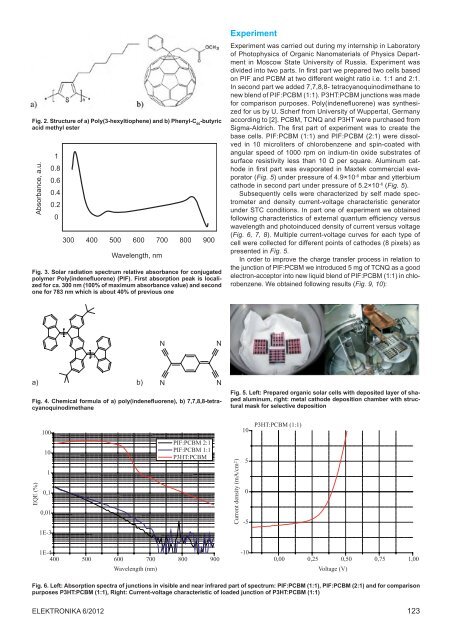
Fig. 6. Left: Absorption spectra <strong>of</strong> junctions in visible and near infrared part <strong>of</strong> spectrum: PIF:PCBM (1:1), PIF:PCBM (2:1) and for comparison<br />
purposes P3HT:PCBM (1:1), Right: Current-voltage characteristic <strong>of</strong> loaded junction <strong>of</strong> P3HT:PCBM (1:1)<br />
Elektronika 6/2012 123


