

Proceedings of the European Summer School of Photovoltaics 4 â 7 ...
Proceedings of the European Summer School of Photovoltaics 4 â 7 ...
Proceedings of the European Summer School of Photovoltaics 4 â 7 ...

You also want an ePaper? Increase the reach of your titles
YUMPU automatically turns print PDFs into web optimized ePapers that Google loves.
Fig. 1. (A) Schematic representation <strong>of</strong> a dye-sensitised solar cell and<br />
(B) <strong>the</strong> chain <strong>of</strong> reactions (transmission <strong>of</strong> an electron) leading to<br />
energy conversion (see text for details) [9]<br />
being. Eventually, various dyes can be tried out in <strong>the</strong> setup to<br />
improve <strong>the</strong> efficiency <strong>of</strong> <strong>the</strong> photon absorption and charge separation<br />
steps.<br />
The Concept <strong>of</strong> Bulk Heterojunction<br />
Chromophores in DSSCs have much greater absorption coefficient<br />
than crystalline silicon. However, a single dye layer on <strong>the</strong><br />
semiconductor surface has proven not to be sufficient. This is because<br />
full coverage <strong>of</strong> <strong>the</strong> surface is difficult to achieve and, what<br />
is more, <strong>the</strong> optically-active area <strong>of</strong> <strong>the</strong> molecule is smaller than<br />
<strong>the</strong> molecule itself. Thus a thicker layer <strong>of</strong> <strong>the</strong> chromophores is<br />
needed. As a junction in planar configuration is not able to meet<br />
this requirement, <strong>the</strong> concept <strong>of</strong> a “bulk (hetero)junction” [1] has<br />
been introduced (also used in all-organic solar cells [10]) (Fig. 2).<br />
As <strong>the</strong> molecules need to have contact with both <strong>the</strong> semiconductor<br />
and <strong>the</strong> electrolyte in order to be able to play <strong>the</strong>ir role,<br />
<strong>the</strong> bulk junction effect is achieved by using mesoscopic titanium<br />
dioxide nanocrystals. This leads to a tremendous increase in <strong>the</strong><br />
interface surface (approximately by a factor <strong>of</strong> 1000). Because <strong>of</strong><br />
this, light rays propagating perpendicularly to <strong>the</strong> surface cross<br />
many molecules increase <strong>the</strong> chance <strong>of</strong> incident photons being<br />
absorbed. Experimental results show that 97.5% <strong>of</strong> <strong>the</strong> 500 nm<br />
light is absorbed by a 12 μm dyed mesoporous titania film [11].<br />
However, too thick a layer forces electrons to make a longer way<br />
to be withdrawn from <strong>the</strong> cell, increasing <strong>the</strong> probability <strong>of</strong> recombination.<br />
Moreover, it slows down diffusion inside <strong>the</strong> pores<br />
– experimental results show that <strong>the</strong> diffusion coefficient <strong>of</strong> <strong>the</strong> I − 3<br />
ion in acetonitrile in a 55% porous TiO 2<br />
membrane decreases by<br />
an order <strong>of</strong> magnitude with respect to free diffusion in <strong>the</strong> same<br />
solvent [5]. Because <strong>of</strong> this trade-<strong>of</strong>f, precise optimisation <strong>of</strong> <strong>the</strong><br />
thickness <strong>of</strong> <strong>the</strong> titania layer is necessary.<br />
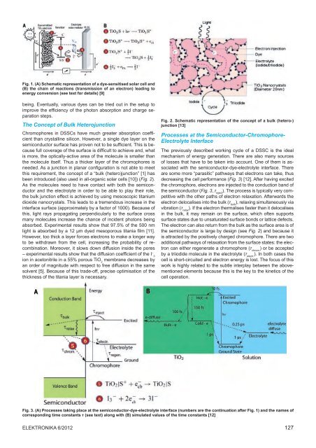
Fig. 2. Schematic representation <strong>of</strong> <strong>the</strong> concept <strong>of</strong> a bulk (hetero‐)<br />
junction [13]<br />
Processes at <strong>the</strong> Semiconductor-Chromophore-<br />
Electrolyte Interface<br />
The previously described working cycle <strong>of</strong> a DSSC is <strong>the</strong> ideal<br />
mechanism <strong>of</strong> energy generation. There are also many sources<br />
<strong>of</strong> losses that have to be taken into account. One <strong>of</strong> <strong>the</strong>m is associated<br />
with <strong>the</strong> semiconductor-dye-electrolyte interface. There<br />
are some more “parasitic” pathways that electrons can take, thus<br />
decreasing <strong>the</strong> cell performance (Fig. 3) [12]. After having excited<br />
<strong>the</strong> chromophore, electrons are injected to <strong>the</strong> conduction band <strong>of</strong><br />
<strong>the</strong> semiconductor (Fig. 3, τ inject<br />
). The process is typically very competitive<br />
with <strong>the</strong> o<strong>the</strong>r paths <strong>of</strong> electron relaxation. Afterwards <strong>the</strong><br />
electron delocalises into <strong>the</strong> bulk (τ bulk<br />
), relaxing simultaneously via<br />
vibration (τ relax<br />
). If <strong>the</strong> electron <strong>the</strong>rmalises faster than it delocalises<br />
in <strong>the</strong> bulk, it may remain on <strong>the</strong> surface, which <strong>of</strong>ten supports<br />
surface states due to unsaturated surface bonds or lattice defects.<br />
The electron can also return from <strong>the</strong> bulk as <strong>the</strong> surface area is <strong>of</strong><br />
<strong>the</strong> semiconductor is large by design (see Fig. 2) and because it<br />
is attracted by <strong>the</strong> positively charged chromophore. There are two<br />
additional pathways <strong>of</strong> relaxation from <strong>the</strong> surface states: <strong>the</strong> electron<br />
can ei<strong>the</strong>r regenerate a chromophore (τ chrom.<br />
) or be accepted<br />
by a triiodide molecule in <strong>the</strong> electrolyte (τ electr.<br />
). In both cases <strong>the</strong><br />
cell is short-circuited and electron energy is lost. The focus <strong>of</strong> this<br />
work is highly related to <strong>the</strong> subtle interplay between <strong>the</strong> abovementioned<br />
elements because this is <strong>the</strong> key to <strong>the</strong> kinetics <strong>of</strong> <strong>the</strong><br />
cell operation.<br />
Fig. 3. (A) Processes taking place at <strong>the</strong> semiconductor-dye-electrolyte interface (numbers are <strong>the</strong> continuation after Fig. 1) and <strong>the</strong> names <strong>of</strong><br />
corresponding time constants τ (see text) along with (B) simulated values <strong>of</strong> <strong>the</strong> time constants [12]<br />
Elektronika 6/2012 127


