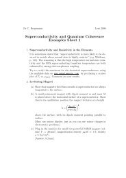
Set of supplementary notes.
Set of supplementary notes.
Set of supplementary notes.

You also want an ePaper? Increase the reach of your titles
YUMPU automatically turns print PDFs into web optimized ePapers that Google loves.
ucture ose, Gate discussed 1 <strong>of</strong> very completes low The resistivity metal<br />
the structure.<br />
area material, <strong>of</strong> the gate at forms the gate a capacitor is increased, with the<br />
potential negative (see charge Figure “induced” 5). Positive incharges at the metal side<br />
) depletion is from one region sideto spread insulating The mostly substrate, layers into the and which n-type the functions semiconductor the as Gate semiconductor 2 channel. <strong>of</strong> Figure The 1, increases ismetal<strong>of</strong> until the metal-oxide the region capacitor beneath induce the a corresponding negative<br />
o most which cases an n-type the gates area <strong>of</strong> relatively internally is the top low connected plate; resistivity the material substrate oxide to maximize material effectively gain. and becomes For channel the are an charge n-type at the semiconductor region, side. As the positive charge<br />
tetrode is then device diffusedcan be the same realized bottom purpose, by plate. not Gate making 1 is <strong>of</strong> very and low current resistivity can material, flow between at drain the gate and is source increased, through the the negative charge “induced” in<br />
l ct connection. metallization allowing For the structure depletion region <strong>of</strong> Figure to spread “induced” 4, consider mostly channel. into a the positive n-type In other gatethe words, semiconductor drain current increases flow until is the region beneath the<br />
<br />
potential channel. In<br />
(see most Figure cases 5). the Positive gates are<br />
“enhanced” charges internally<br />
by at connected the gate metal potential. sideoxide effectively becomes an n-type semiconductor region,<br />
Thus drain current flow can<br />
2 <strong>of</strong> Figure 1, is <strong>of</strong> together. the metal-oxide A tetrode capacitor device can induce be realized<br />
be modulated a corresponding by not making<br />
by the gate negativeand current can flow between drain and source through the<br />
voltage; i.e. the channel resistance<br />
this internal connection.<br />
“induced” channel. In other words, drain current flow is<br />
ize gain. For the<br />
<br />
<br />
“enhanced” by the gate potential. Thus drain current flow can<br />
sistivity material, at the gate is increased, the negative may be changed charge “induced” to a p-channel in<br />
be modulated device by by the reversing gate voltage; the i.e. the channel resistance<br />
tly into the n-type the semiconductor <br />
material types.<br />
<br />
<br />
increases until the region beneath theis directly related to the gate voltage. The n-channel structure<br />
rnally connected oxide effectively becomes an n-type semiconductor region, may be changed<br />
<br />
to a p-channel device by reversing the<br />
d by not making and current can flow between drain and source through the<br />
<br />
<br />
material types.<br />
<br />
<br />
<br />
<br />
“induced” channel. In other words, drain current flow is<br />
<br />
<br />
<br />
“enhanced” by the gate potential. Thus drain current flow can<br />
<br />
<br />
<br />
be modulated by the gate voltage; i.e. the channel resistance<br />
<br />
is directly related to the gate voltage. The n-channel structure<br />
<br />
<br />
may be changed to a p-channel device by reversing the<br />
material types. <br />
<br />
<br />
<br />
<br />
<br />
<br />
<br />
D-EFFECT TRANSISTORS (MOSFET)<br />
<br />
<br />
<br />
<br />
MOS FIELD-EFFECT TRANSISTORS (MOSFET)<br />
al-oxide-semiconductor (MOSFET) operates with<br />
<br />
<br />
<br />
<br />
fferent control mechanism The than metal-oxide-semiconductor the JFET. Figure (MOSFET) operates with<br />
<br />
<br />
he development.<br />
<br />
<br />
The a substrate slightly different may be control highmechanism than the JFET. Figure<br />
-type material, as for the 4 2N4351. shows the This development. time two The substrate may be high<br />
<br />
resistivity p-type material, as for the 2N4351. This time two<br />
<br />
w-resistivity n-type regions (source and drain) are<br />
<br />
<br />
the<br />
<br />
separate low-resistivity n-type regions<br />
substrate as shown in Figure 4b. Next, the<br />
Figure (source 3. and Junction drain) are<br />
<br />
FET with Single-Ended Geometry<br />
diffused into the substrate as shown in Figure 4b. Next, the<br />
Figure 3. Junction FET with Single-Ended Geometry<br />
<br />
he structure is covered with an insulating oxide <br />
<br />
a<br />
(MOSFET)<br />
surface <strong>of</strong> the structure is covered with an insulating oxide<br />
nitride layer. The oxide layer serves as a <br />
<br />
bulklayer semiconductor<br />
and a nitride layer.<br />
crystal<br />
The oxide<br />
allows<br />
layer serves<br />
comparatively<br />
as a<br />
<br />
oating for the FET surface and to insulate the<br />
simple manufacture <strong>of</strong> a JFET.<br />
T) operates with protective coating for the FET surface and to insulate the<br />
<br />
<br />
m the gate. However the oxide is subject to<br />
<br />
the JFET. Figure channel from the gate. However the oxide is subject to<br />
<br />
<br />
on e may by sodium be high ions which contamination are found by in sodium varyingions which are found in varying<br />
n all environments. Such quantities contamination all environments. results Such contamination results <br />
<br />
<br />
1. This time two<br />
ce instability and drain) and are changes in in long device term characteristics.<br />
instability and changes in device characteristics.<br />
<br />
<br />
<br />
<br />
ure e is 4b. impervious Next, theto sodium Silicon Figure ions nitride and 3. Junction thus is impervious is used FET to with sodium Single-Ended <br />
ions and thus<br />
Geometry<br />
is used <br />
to shield the oxide layer from contamination. <br />
e insulating oxide layer oxide from contamination. Holes are cut<br />
Holes are cut<br />
<br />
into the oxide and nitride layers allowing metallic contact to<br />
de er and serves nitride as layers a allowing metallic contact to<br />
the source and drain. Then, the gate metal area is overlaid<br />
d and to drain. insulate Then, the the gate on metal the insulation, area is overlaid covering the entire channel region <br />
<br />
and, <br />
de<br />
lation,<br />
is subject<br />
covering<br />
to<br />
the entire simultaneously, channel region metal and, contacts to the drain and <br />
<br />
<br />
source are<br />
<br />
<br />
<br />
found<br />
sly, metal<br />
in varying<br />
contacts to the made drain as shown and source in Figure are4d. The contact to the metal<br />
<br />
area<br />
<br />
own<br />
mination<br />
in Figure<br />
results<br />
4d. The contact covering to the the channel metal area is the gate terminal. Note that there<br />
<br />
<br />
e<br />
channel<br />
characteristics.<br />
is the gate terminal. is no physical Note penetration that there<strong>of</strong> the metal through the oxide and<br />
<br />
<br />
and<br />
al penetration<br />
thus is used<br />
<strong>of</strong> the metal nitride through into the substrate. oxide<br />
<br />
andSince the drain and source are Figure 4. Development <strong>of</strong> Enhancement-Mode<br />
<br />
the substrate. Since the isolated drain by and the source substrate, <br />
areany drain-to-source Figure current 4. Development in the <strong>of</strong> Enhancement-Mode N-Channel MOSFET<br />
n. Holes are cut<br />
<br />
the substrate, any drain-to-source current in the<br />
N-Channel MOSFET<br />
etallic contact to<br />
l area is overlaid<br />
very high intrinsic source-drain resistance.<br />
<br />
nnel region and,<br />
<br />
<br />
and source are<br />
<br />
<br />
o the metal area<br />
Note that there<br />
<br />
<br />
gh the oxide and<br />
and source are establishes a conducting channel between source and drain.<br />
ce current in the<br />
nc...<br />
Freescale Semiconductor, I<br />
charge<br />
8.4.<br />
at the semiconductor side.<br />
FIELD EFFECT TRANSISTOR is directly As the related positive to the charge gate voltage. The n-channel structure<br />
117<br />
Figure 8.16: Fabrication <strong>of</strong> a JFET: doping an annular p-type region into an otherwise n-type<br />
Figure 8.17: Manufacture <strong>of</strong> an enhancement-mode n-channel MOSFET: a) p−doped substrate,<br />
b) n−doped source and drain contacts. The depletion zones around these contacts produces<br />
c) Insulating oxide layer (silicon nitride guards<br />
against sodium diffusing in). d) Metallic contacts to source and drain are made through holes<br />
which are etched into the insulating layer, the metallic gate electrode is insulated from the<br />
substrate. Applying a positive voltage to the gate pulls electrons into the depletion zones and<br />
Figure 4. Development <strong>of</strong> Enhancement-Mode<br />
N-Channel MOSFET<br />
2 For More Information MOTOROLA On This SEMICONDUCTOR Product, APPLICATION INFORMATION<br />
Go to: www.freescale.com<br />
For More Information MOTOROLA On This SEMICONDUCTOR Product, APPLICATION INFORMATION<br />
Go to: www.freescale.com<br />
Pinch-<strong>of</strong>f: At finite drain-source current, the potential in the channel changes along the<br />
channel – it drops from drain to source. This causes the width <strong>of</strong> the depletion zone to change<br />
along the channel. The depletion zone is be widest at the drain end, because there the potential<br />
<strong>of</strong> the n-type channel is highest, and so the voltage between a positively charged gate and the<br />
channel is lowest there. If we increase the drain-source voltage while keeping the gate potential<br />
ore Information MOTOROLA On This SEMICONDUCTOR Product, APPLICATION INFORMATION<br />
Go to: www.freescale.com<br />
constant, then the depletion zone will widen near the drain electrode, until it eventually covers<br />
most <strong>of</strong> the width <strong>of</strong> the semiconductor at that point, pinching <strong>of</strong>f the conducting channel.<br />
Plotting the I − V characteristic, drain-source current I D as a function <strong>of</strong> drain-source voltage<br />
V DS , at constant gate-source voltage V GS (Fig. 8.15) therefore shows saturation <strong>of</strong> I D at high<br />
V DS .<br />
Amplifier: The saturation <strong>of</strong> the drain-source current at a level depending on V GS is the<br />
basis for operating the JFET as an amplifier: we can control the current through the device<br />
by changing the gate voltage, without having to worry about keeping the drain-source voltage<br />
exactly constant. Basically, the JFET acts like a voltage-controlled current source.