

TPF-C Technology Plan - Exoplanet Exploration Program - NASA
TPF-C Technology Plan - Exoplanet Exploration Program - NASA
TPF-C Technology Plan - Exoplanet Exploration Program - NASA

You also want an ePaper? Increase the reach of your titles
YUMPU automatically turns print PDFs into web optimized ePapers that Google loves.
Error Budgets<br />
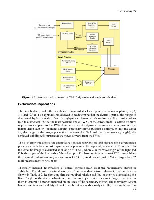
Figure 2-3. Models used to create the <strong>TPF</strong>-C dynamic and static error budget.<br />
Performance Implications<br />
The error budget enables the calculation of contrast at selected points in the image plane (e.g., 3,<br />
3.5, and 4λ/D). This approach has allowed us to determine that the dynamic part of the budget is<br />
dominated by beam walk. Both throughput and low-order aberration stability considerations<br />
lead to a practical limit to the inner working angle (IWA) of the coronagraph. Contrast stability<br />
requirements applied to the IWA then determine the dynamic engineering requirements (e.g.<br />
mirror shape stability, pointing stability, secondary mirror position stability). Within the target<br />
angular range in the image plane (i.e., between the IWA and the outer working angle), the<br />
achieved stability will improve as we move outward from the IWA.<br />
The <strong>TPF</strong> error tree depicts the quantitative contrast contributions and margins for a given image<br />
plane point with the contrast requirements appearing at the top level, as shown in Figure 2-1. In<br />
this case the image is evaluated at an angle of 4 λ/D, where λ is the wavelength of the light and<br />
D is the length of the long axis of the telescope. The baseline 8-m version of <strong>TPF</strong> must achieve<br />
the required contrast working as close in as 4 λ/D to provide an adequate IWA no larger than 62<br />
milli-arcsecs (mas) at λ=600 nm.<br />
Thermally induced deformations of optical surfaces must meet the requirements shown in<br />
Table 2-1. The allowed structural motions of the secondary mirror relative to the primary are<br />
shown in Table 2-2. Recognizing that the required relative stability of their positions along the<br />
line of sight to the star is sub-micron, we plan to implement a laser metrology truss between<br />
them to control a hexapod mounted on the back of the secondary mirror. The metrology system<br />
has a resolution and stability of ~200 pm, but it responds slowly (


