

TPF-C Technology Plan - Exoplanet Exploration Program - NASA
TPF-C Technology Plan - Exoplanet Exploration Program - NASA
TPF-C Technology Plan - Exoplanet Exploration Program - NASA

You also want an ePaper? Increase the reach of your titles
YUMPU automatically turns print PDFs into web optimized ePapers that Google loves.
Optics and Starlight Suppression <strong>Technology</strong><br />
3.1.2 <strong>Technology</strong> Demonstration Mirror<br />
Objective<br />
The TDM is a 1.8-m mirror that will demonstrate mirror technology required for the primary<br />
mirror (PM). The static error budget for the entire system requires sub-nm wavefront quality, and<br />
the dynamic error budget is two orders of magnitude more stringent for <strong>TPF</strong>-C. For both static<br />
and dynamic errors the PM is expected to be the largest error contributor. Errors on the primary<br />
mirror must be within the capture range for the wavefront sensing and control system. Control<br />
of the deformable mirror is then relied upon to reduce the WFE to the required sub-nm level. The<br />
technology necessary to control these errors for the large <strong>TPF</strong>-C can be demonstrated on a 1.8m<br />
sub-scale mirror if it is a light-weighted, off-axis optic like the PM. For both the TDM and <strong>TPF</strong>-<br />
C static errors will be driven by the structural design, figuring and polishing techniques, coating<br />
process, and the sensitivity of the metrology to these errors. Dynamic errors like the static errors<br />
are driven primarily by the structural design but also by material characteristics and fabrication<br />
processes. Timing of the TDM is very important so that technology risks are reduced before the<br />
fabrication of the <strong>TPF</strong>-C PM. Due to the long lead time for fabrication of the PM, it must be<br />
procured early in the formulation phase if <strong>TPF</strong>-C is to meet its launch readiness date. <strong>TPF</strong>-C<br />
performance requires that mirror technology sufficient to achieve the required levels, as outlined<br />
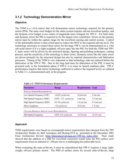
in Table 3-1, is demonstrated early in the program.<br />
Table 3-1. TDM Performance Requirements<br />
Parameter Range Requirement Goal<br />
SURFACE ERROR REQUIREMENTS<br />
Low Spatial Frequency (LSF) 10 cycles/cm 10 Å rms 5 Å rms<br />
COATING RESIDUAL REFLECTANCE REQUIREMENTS<br />
Mid Spatial Frequency 0.025–0.5 cycles/cm


