Câ¢CURE® 800/8000 9.4 apC/8X Technical Manual - Tyco Security ...
Câ¢CURE® 800/8000 9.4 apC/8X Technical Manual - Tyco Security ...
Câ¢CURE® 800/8000 9.4 apC/8X Technical Manual - Tyco Security ...
You also want an ePaper? Increase the reach of your titles
YUMPU automatically turns print PDFs into web optimized ePapers that Google loves.
Wiring for Relay Outputs<br />
Wiring for Relay Outputs<br />
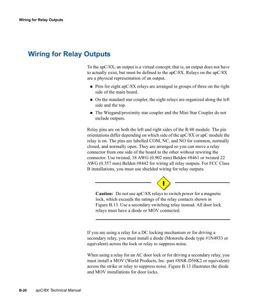
To the <strong>apC</strong>/<strong>8X</strong>, an output is a virtual concept; that is, an output does not have<br />
to actually exist, but must be defined to the <strong>apC</strong>/<strong>8X</strong>. Relays on the <strong>apC</strong>/<strong>8X</strong><br />
are a physical representation of an output.<br />
• Pins for eight <strong>apC</strong>/<strong>8X</strong> relays are arranged in groups of three on the right<br />
side of the main board.<br />
• On the standard star coupler, the eight relays are organized along the left<br />
side and the top.<br />
• The Wiegand/proximity star coupler and the Mini Star Coupler do not<br />
include outputs.<br />
Relay pins are on both the left and right sides of the R/48 module. The pin<br />
orientations differ depending on which side of the <strong>apC</strong>/<strong>8X</strong> or <strong>apC</strong> module the<br />
relay is on. The pins are labelled COM, NC, and NO for common, normally<br />
closed, and normally open. They are arranged so you can move a relay<br />
connector from one side of the board to the other without rewiring the<br />
connector. Use twisted, 18 AWG (0.902 mm) Belden #8461 or twisted 22<br />
AWG (0.357 mm) Belden #8442 for wiring all relay outputs. For FCC Class<br />
B installations, you must use shielded wiring for relay outputs.<br />
Caution: Do not use <strong>apC</strong>/<strong>8X</strong> relays to switch power for a magnetic<br />
lock, which exceeds the ratings of the relay contacts shown in<br />
Figure B.13. Use a secondary switching relay instead. All door lock<br />
relays must have a diode or MOV connected.<br />
If you are using a relay for a DC locking mechanism or for driving a<br />
secondary relay, you must install a diode (Motorola diode type #1N4933 or<br />
equivalent) across the lock or relay to suppress noise.<br />
When using a relay for an AC door lock or for driving a secondary relay, you<br />
must install a MOV (World Products, Inc. part #SNR-D56K2 or equivalent)<br />
across the strike or relay to suppress noise. Figure B.13 illustrates the diode<br />
and MOV installations for door locks.<br />
B-20 <strong>apC</strong>/<strong>8X</strong> <strong>Technical</strong> <strong>Manual</strong>


