Câ¢CURE® 800/8000 9.4 apC/8X Technical Manual - Tyco Security ...
Câ¢CURE® 800/8000 9.4 apC/8X Technical Manual - Tyco Security ...
Câ¢CURE® 800/8000 9.4 apC/8X Technical Manual - Tyco Security ...

Create successful ePaper yourself
Turn your PDF publications into a flip-book with our unique Google optimized e-Paper software.
Wiring Card Readers<br />
Every input device, including door contacts, exit request inputs, or standard<br />
monitoring equipment, has a unique input number determined by the <strong>apC</strong>/<strong>8X</strong><br />
pins to which it connects. Input pins are located on the card reader modules,<br />
the I/32 optional module, and the RM Input Module.<br />
Note:<br />
FCC Class B Installations require shielded wire.<br />
<strong>apC</strong>/<strong>8X</strong> or <strong>apC</strong> Inputs<br />
IN1 through IN8, corresponding to P9 through P16, are eight supervised<br />
inputs. The star coupler adds unsupervised inputs IN9 through IN16.<br />
Each Wiegand/proximity star coupler module (upper and lower) provides one<br />
supervised input for each reader. Combining these eight supervised inputs<br />
with the eight supervised inputs on the <strong>apC</strong>/<strong>8X</strong> main board provides a total of<br />
two supervised inputs for each reader. Output relays are not provided on the<br />
WPSC module set. Instead, use the eight on-board <strong>apC</strong>/<strong>8X</strong> relays or R/8<br />
modules.<br />
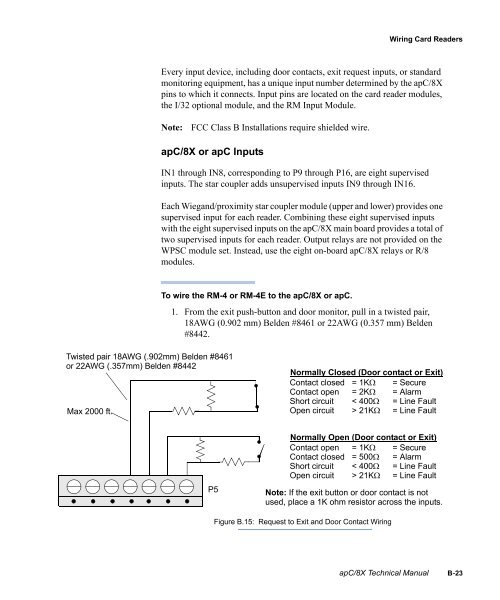
To wire the RM-4 or RM-4E to the <strong>apC</strong>/<strong>8X</strong> or <strong>apC</strong>.<br />
1. From the exit push-button and door monitor, pull in a twisted pair,<br />
18AWG (0.902 mm) Belden #8461 or 22AWG (0.357 mm) Belden<br />
#8442.<br />
Twisted pair 18AWG (.902mm) Belden #8461<br />
or 22AWG (.357mm) Belden #8442<br />
Max 2000 ft.<br />
Normally Closed (Door contact or Exit)<br />
Contact closed<br />
Contact open<br />
Short circuit<br />
Open circuit<br />
= 1KΩ<br />
= 2KΩ<br />
< 400Ω<br />
> 21KΩ<br />
= Secure<br />
= Alarm<br />
= Line Fault<br />
= Line Fault<br />
P5<br />
Normally Open (Door contact or Exit)<br />
Contact open<br />
Contact closed<br />
Short circuit<br />
Open circuit<br />
= 1KΩ<br />
= 500Ω<br />
< 400Ω<br />
> 21KΩ<br />
= Secure<br />
= Alarm<br />
= Line Fault<br />
= Line Fault<br />
Note: If the exit button or door contact is not<br />
used, place a 1K ohm resistor across the inputs.<br />
Figure B.15: Request to Exit and Door Contact Wiring<br />
<strong>apC</strong>/<strong>8X</strong> <strong>Technical</strong> <strong>Manual</strong> B-23