Service Manual - AMS Neve
Service Manual - AMS Neve
Service Manual - AMS Neve

Create successful ePaper yourself
Turn your PDF publications into a flip-book with our unique Google optimized e-Paper software.
SynchroNet ES/2 <strong>Service</strong> <strong>Manual</strong><br />
CIRCUIT DESCRIPTION<br />
Timecode interface<br />
LTC reader<br />
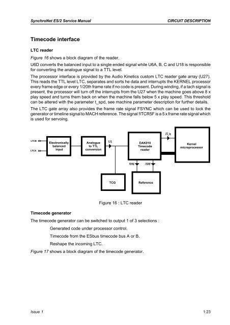
Figure 16 shows a block diagram of the reader.<br />
U6D converts the balanced input to a single ended signal while U6A, B, C and U18 is responsible<br />
for converting the analogue signal to a TTL level.<br />
The processor interface is provided by the Audio Kinetics custom LTC reader gate array (U27).<br />
This reads the TTL level LTC, separates and sorts he data and interrupts the KERNEL processor<br />
every frame edge or every 1/20th frame rate if no code is present. During winding, if a tach signal is<br />
present, the processor will turn off the interrupts from the U27 when the machine goes above 8 x<br />
play speed and turns them back on when the machine falls below 5 x play speed. This threshold<br />
can be altered with the parameter t_spd, see machine parameter description for further details.<br />
The LTC gate array also provides the frame rate signal FSYNC which can be used to lock the<br />
generator or timeline signal to MACH reference. The signal !ITCR5F isa5xframe rate signal which<br />
is used for servoing.<br />
LTC_irq<br />
LTCB<br />
LTCA<br />
Electronically<br />
balanced<br />
input<br />
Analogue<br />
to TTL<br />
conversion<br />
TLTC<br />
DAK010<br />
Timecode<br />
reader<br />
Kernel<br />
microprocessor<br />
FSYNC<br />
iTCR5F<br />
TCG<br />
Reference<br />
Figure 16 : LTC reader<br />
Timecode generator<br />
The timecode generator can be switched to output 1 of 3 selections :<br />
Generated code under processor control.<br />
Timecode from the ESbus timecode bus A or B.<br />
Reshape the incoming LTC.<br />
Figure 17 shows a block diagram of the timecode generator.<br />
Issue 1 1:23