Service Manual - AMS Neve
Service Manual - AMS Neve
Service Manual - AMS Neve

Create successful ePaper yourself
Turn your PDF publications into a flip-book with our unique Google optimized e-Paper software.
SynchroNet ES/2 <strong>Service</strong> <strong>Manual</strong><br />
ES/2 TEST SOFTWARE<br />
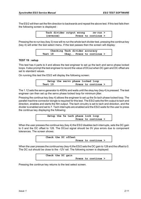
The ES/2 will then set the film direction to backwards and repeat the above test. If this test fails then<br />
the following screen is displayed :<br />
Tach divider output wrong re-run ><br />
(reverse) Press to continue ><br />
Pressing the re-run key (key 3) now will re-run the whole tach divider test, pressing the continue key<br />
(key 4) will enter the test select menu. If the test passes then the screen will display:<br />
TEST 19 : setup<br />
Checking Tach divider accuracy<br />
Test 18 Okay.. Press to continue ><br />
This test has 4 parts to it and allows the test engineer to set up the tach and servo phase locked<br />
loops. It also prompt the test engineer to record the value of DCout when DC gain and DC offset are<br />
set to standard values.<br />
On running this test the ES/2 will display the following screen:<br />
Setup the servo phase locked loop<br />
Test 19 Press to continue ><br />
The 1.12 sets the servo generator to 400Hz and waits until the okay key (key 4) is pressed. The test<br />
engineer can then set up the servo phase locked loop for minimum jitter.<br />
Pressing the continue key (key 4) allows the engineer to set up the 5x tach phase locked loop. The<br />
parallel machine connector dongle is required for this test. The ES/2 sets the film output to tach and<br />
direction, enables and starts the film output. The tach circuitry is set to tach and direction, and the<br />
divider is enabled and set to 7. Tach interrupts are enabled and the ES/2 waits for the user to press<br />
the continue key displaying the following:<br />
Setup the 5x tach phase lock loop<br />
Press to continue ><br />
When the user presses the continue key (key 4) the ES/2 disables tach interrupts, sets the DC gain<br />
to 0 and the DC offset to 128. The DCout signal should be 0V plus errors due to component<br />
tolerances. The screen shows:<br />
Check the DC offset<br />
Press to continue ><br />
When the user presses the continue key (key 4) the ES/2 sets the DC gain to 128 and the offset to 0.<br />
The DC out should be close to the -12V rail. The following screen is displayed:<br />
Check the DC gain<br />
Press to continue ><br />
Pressing the continue key returns to the test select screen.<br />
Issue 1 2:11