


Create successful ePaper yourself
Turn your PDF publications into a flip-book with our unique Google optimized e-Paper software.
MULTICYLINDER ENGINES 109<br />
CYLINDER HEAD<br />
TIGHTENING SEQUENCE<br />
P'<br />
Screw<br />
Flywheel<br />
Flywheel<br />
Gear<br />
20. Adjust the valve clearance as described in Chapter<br />
Three.<br />
2 1. Reinstall the valve cover.<br />
ROCKER SHAFT ASSEMBLY<br />
12. Install the rocker assembly and the rocker arm stand<br />
retaining nuts (Figure 10). Tighten the nuts to 37 N*m (27<br />
ft.-lb.).<br />
13. Install the fuel injector and precombustion chamber<br />
as described in Chapter Seven.<br />
14. Install the exhaust manifold.<br />
15. Install the air cleaner base and the air cleaner.<br />
16. Connect the wire lead to the water temperature sender<br />
(Figure 9).<br />
17A. Engines with standard cooling-Connect the lower<br />
water hose (Figure 9).<br />
17B. Engines with freshwater (closed) cooling system-Install<br />
the freshwater pump as described in Chapter<br />
Eight.<br />
18. Install the alternator.<br />
19. If the engine is installed in the boat, proceed as follows:<br />
a. Attach the exhaust hose to the exhaust elbow.<br />
b. On engines equipped with a closed cooling system,<br />
fill the cooling system as described in Chapter Four.<br />
c. Connect the negative battery cable to the negative<br />
battery terminal.<br />
Each valve is actuated by a rocker arm that rides on a<br />
shaft (Figure 8). Each rocker arm is equipped with a<br />
bushing in the rocker arm bore. A snap ring at each end of<br />
the rocker arm shaft retains the rocker arms on the rocker<br />
shafts.<br />
1. Remove the valve cover as previously described.<br />
2. Remove the rocker arm stand retaining nuts (Figure<br />
lo), then remove the rocker shaft assembly.<br />
NOTE<br />
The rocker arms on 2GM and 2GM20 engines<br />
are identical, but rocker arms on<br />
3GM, 3GM30, 3HM and 3HM35 engines<br />
are designed for use with the intake or exhaust<br />
valves.<br />
3. Remove the snap rings at both ends of the rocker shaft<br />
and remove the rocker shaft components.<br />
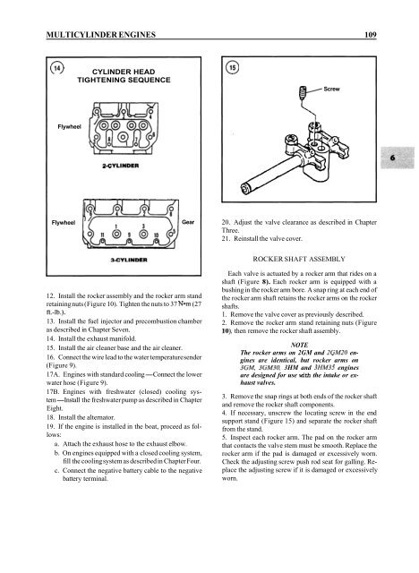
4. If necessary, unscrew the locating screw in the end<br />
support stand (Figure 15) and separate the rocker shaft<br />
from the stand.<br />
5. Inspect each rocker arm. The pad on the rocker arm<br />
that contacts the valve stem must be smooth. Replace the<br />
rocker arm if the pad is damaged or excessively worn.<br />
Check the adjusting screw push rod seat for galling. Replace<br />
the adjusting screw if it is damaged or excessively<br />
worn.


