


Create successful ePaper yourself
Turn your PDF publications into a flip-book with our unique Google optimized e-Paper software.
TRANSMISSION-KM SERIES 207<br />
Neutral hole<br />
I<br />
h. Tighten the nut (left-hand threads) to the torque<br />
specified in Table 2.<br />
i. Make sure the gears rotate freely.<br />
j. Stake the nut to lock the nut in place.<br />
Shifter (KM2A, KM2C and KM3A models)<br />
Refer to Figure 20.<br />
1. Ifnot previously removed, detach the cotter pin and remove<br />
the actuator from the shift lever.<br />
2. Remove the shifter.<br />
~eutra'l notch<br />
NOTE<br />
Make alignment marks on the shift lever and<br />
shift shaft so the shift lever can be reinstalled<br />
in its original position.<br />
3. Loosen the clamp bolt and remove the shift lever.<br />
I t 5 mm (0.20 in.)<br />
a. If reinstalling the original clutch cone, install it in its<br />
original position-forward end toward the forward<br />
gear.<br />
b. Install the pin before installing the inner roller bearing<br />
race.<br />
c. Use a suitable tool or sleeve to drive the inner roller<br />
bearing race onto the shaft. Do not use excessive<br />
force. Drive the race onto the shaft until it bottoms.<br />
d. Use a suitable tool or sleeve to drive the tapered<br />
roller bearing onto the shaft. Do not use excessive<br />
force. Drive the bearing onto the shaft until it bottoms.<br />
e. On KM2P and KM3P transmissions-Install the<br />
spring cups so the cupped side is toward the gear.<br />
f. Install each thick thrust washer so the stepped side<br />
is toward the tapered roller bearing.<br />
g. Install the washer so the pin in the output shaft fits<br />
in the groove in the washer.<br />
NOTE<br />
The setscrew and plug contain the springs<br />
and mayfly out.<br />
4. Remove the setscrew and plug, then remove the<br />
springs and detent pins.<br />
5. Remove the shifter shaft.<br />
6. Remove and discard the O-ring.<br />
7. Use a screwdriver or suitable tool to pry out the seal.<br />
Be careful not to damage the bearing.<br />
8. Inspect the bearing. If it is faulty, replace it as follows:<br />
a. Heat the shifter body to 2 12O F (1 00° C), then drive<br />
out the bearing.<br />
b. Install the new bearing with the stamped end out.<br />
Push in the bearing until it bottoms.<br />
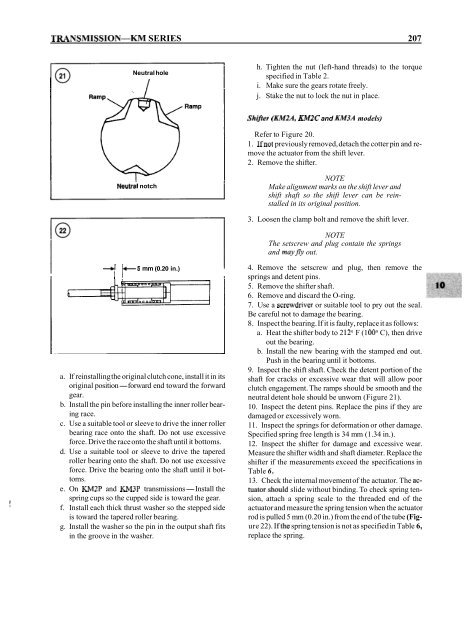
9. Inspect the shift shaft. Check the detent portion of the<br />
shaft for cracks or excessive wear that will allow poor<br />
clutch engagement. The ramps should be smooth and the<br />
neutral detent hole should be unworn (Figure 21).<br />
10. Inspect the detent pins. Replace the pins if they are<br />
damaged or excessively worn.<br />
11. Inspect the springs for deformation or other damage.<br />
Specified spring free length is 34 mm (1.34 in.).<br />
12. Inspect the shifter for damage and excessive wear.<br />
Measure the shifter width and shaft diameter. Replace the<br />
shifter if the measurements exceed the specifications in<br />
Table 6.<br />
13. Check the internal movement of the actuator. The actuator.should<br />
slide without binding. To check spring tension,<br />
attach a spring scale to the threaded end of the<br />
actuator and measure the spring tension when the actuator<br />
rod is pulled 5 mm (0.20 in.) from the end of the tube (Figure<br />
22). Ifthe spring tension is not as specified in Table 6,<br />
replace the spring.


