


You also want an ePaper? Increase the reach of your titles
YUMPU automatically turns print PDFs into web optimized ePapers that Google loves.
78 CHAPTER FIVE<br />
5. Remove the valve keys (2, Figure 22) and release the<br />
spring tension.<br />
6. Remove the valve spring retainer and valve spring.<br />
CA UTION<br />
Remove any burrs from the valve stem lock<br />
grooves (Figure 24) before removing the<br />
valve to prevent damage to the valve guide.<br />
7. Remove the valve.<br />
8. Remove and discard the valve stem seal (5, Figure<br />
22).<br />
9. Repeat Steps 3-8 for the remaining valve.<br />
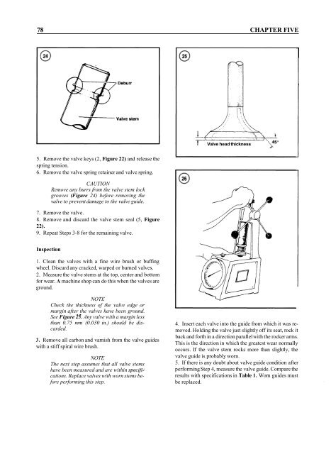
T Valve head thickness<br />
'r-<br />
Inspection<br />
1. Clean the valves with a fine wire brush or buffing<br />
wheel. Discard any cracked, warped or burned valves.<br />
2. Measure the valve stems at the top, center and bottom<br />
for wear. A machine shop can do this when the valves are<br />
ground.<br />
NOTE<br />
Check the thickness of the valve edge or<br />
margin after the valves have been ground.<br />
See Figure 25. Any valve with a margin less<br />
than 0.75 mm (0.030 in.) should be discarded.<br />
3. Remove all carbon and varnish from the valve guides<br />
with a stiff spiral wire brush.<br />
NOTE<br />
The next step assumes that all valve stems<br />
have been measured and are within speczfications.<br />
Replace valves with worn stems before<br />
performing this step.<br />
4. Insert each valve into the guide from which it was removed.<br />
Holding the valve just slightly off its seat, rock it<br />
back and forth in a direction parallel with the rocker arms.<br />
This is the direction in which the greatest wear normally<br />
occurs. If the valve stem rocks more than slightly, the<br />
valve guide is probably worn.<br />
5. If there is any doubt about valve guide condition after<br />
performing Step 4, measure the valve guide. Compare the<br />
results with specifications in Table 1. Worn guides must<br />
be replaced.


