


Create successful ePaper yourself
Turn your PDF publications into a flip-book with our unique Google optimized e-Paper software.
212 CHAPTER TEN<br />
1. Install the input shaft assembly in the transmission<br />
case.<br />
2. Position the transmission case so the open end is up.<br />
3. Install the outer bearing race on the input shaft tapered<br />
bearing.<br />
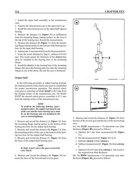
4. Measure the distance (A, Figure 30) in millimeters<br />
from the mounting flange mating surface on the case to<br />
the top of the bearing race. Record the measurement.<br />
5. Measure the distance (B, Figure 31) from the mounting<br />
flange mating surface to the bottom of the bearing race<br />
bore for the input shaft bearing.<br />
6. Subtract the A measurement from the B measurement.<br />
7. From the result obtained in Step 6, subtract 0.0-0.05<br />
mm. This result equals the thickness of the shim(s) that<br />
must be installed in the bearing bore in the mounting<br />
flange.<br />
8. Install the shim(s) in the bearing bore in the mounting<br />
flange, then press the bearing outer race into the mounting<br />
flange on top of the shims. Be sure the race is bottomed.<br />
Output Shaft<br />
In the following procedure to adjust bearing preload,<br />
the neutral position of the clutch cone must be established<br />
for proper transmission operation. The desired clutch<br />
cone groove centerline on Model KM2P is 48.3 mm from<br />
the mating surface of the transmission case. On Model<br />
KM3P the desired clutch groove centerline is 47.3 mm<br />
from the mating surface of the transmission case.<br />
NOTE<br />
To perform the following bearing adjustmentprocedure,<br />
the output shaft must be out<br />
of the case and the outer bearing races must<br />
be on the bearings and not installed in the<br />
case or mountingflange.<br />
1. Measure and record the distance (A, Figure 32) from<br />
the mounting flange mating surface to the bottom of the<br />
bearing race bore for the output shaft bearing.<br />
2. Measure and record the distance (B, Figure 33) from<br />
the mounting surface of the case to the bottom of the bearing<br />
race bore for the output shaft bearing.<br />
3. Measure and record the distance (C, Figure 34) from<br />
the faces of the output shaft bearing races.<br />
NOTE<br />
In Steps 4 and 5, force the gears toward the<br />
cone clutch.<br />
4. Measure and record the distance (D, Figure 34) between<br />
the faces of the forward and reverse gears.<br />
5. Measure and record the distance (E, Figure 34) from<br />
the face of the reverse gear and the face of the rear bearing<br />
race.<br />
6A. On KM2P transmissions-To determine rear shim<br />
thickness (Figure 35), proceed as follows:<br />
a. Subtract 48.3 mm from measurement (B, Figure<br />
33).<br />
b. Divide measurement (D, Figure 34) by 2.<br />
c. Subtract substep b from substep a.<br />
d. Subtract measurement (E, Figure 34) from substep<br />
C.<br />
e. Subtract 0.0-0.05 mm from substep d. The result is<br />
the required rear shim thickness.<br />
6B. On KM3P transmissions-To determine rear shim<br />
thickness (Figure 35), proceed as follows:


