


You also want an ePaper? Increase the reach of your titles
YUMPU automatically turns print PDFs into web optimized ePapers that Google loves.
208 CHAPTER TEN<br />
14. Reassemble the shifter by reversing the disassembly<br />
procedure. Note the following during reassembly:<br />
a. Apply sealant to the detent setscrew threads.<br />
b. Install the shift lever-on the shift shaft while aligning<br />
the marks made during disassembly.<br />
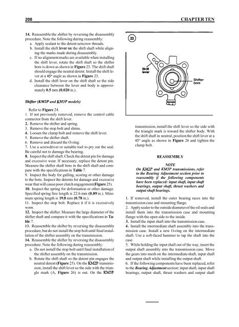
c. If no alignment marks are available when installing<br />
the shift lever, rotate the shift shaft so the shifter<br />
bore is down as shown in Figure 23. The shift shaft<br />
should engage the neutral detent. Install the shift lever<br />
at a 45O angle as shown in Figure 23.<br />
d. Install the shift lever on the shift shaft so the side<br />
clearance between the lever and body is approximately<br />
0.5 mm (0.020 in.).<br />
Shifter<br />
bore<br />
Shifter (KM2P and KM3P models)<br />
Refer to Figure 24.<br />
1. If not previously removed, remove the control cable<br />
connector from the shift lever.<br />
2. Remove the shifter and spring.<br />
3. Remove the stop bolt and shims.<br />
4. Loosen the clamp bolt and remove the shift lever.<br />
5. Remove the shifter shaft.<br />
6. Remove and discard the O-ring.<br />
7. Use a screwdriver or suitable tool to pry out the seal.<br />
Be careful not to damage the bearing.<br />
8. Inspect the shift shaft. Check the detent pin for damage<br />
and excessive wear. If necessary, replace the detent pin.<br />
Measure the shifter shaft bore in the shift shaft and compare<br />
with the specifications in Table 7.<br />
9. Inspect the body for galling, scoring or other damage<br />
to the bore. Inspect the detents for damage and excessive<br />
wear that will cause poor clutch engagement (Figure 25).<br />
10. Inspect the spring for deformation or other damage.<br />
Specified spring free length is 22.6 mm (0.89 in.). Minimum<br />
spring length is 19.8 mm (0.78 in.).<br />
11. Inspect the stop bolt. Replace it if it is excessively<br />
worn.<br />
12. Inspect the shifter. Measure the large diameter of the<br />
shifter shaft and compare it with the specifications in Table<br />
7.<br />
13. Reassemble the shifter by reversing the disassembly<br />
procedure, but do not install the stop bolt until final installation<br />
of the shifter assembly on the transmission.<br />
14. Reassemble the shifter by reversing the disassembly<br />
procedure. Note the following during reassembly:<br />
a. Do not install the stop bolt until final installation of<br />
the shifter assembly on the transmission.<br />
b. Rotate the shift shaft so the detent pin engages the<br />
neutral detent (Figure 25). On the KM2P transmission,<br />
install the shift lever so the side with the triangle<br />
mark (A, Figure 26) is out. On the KM3P<br />
transmission, install the shift lever so the side with<br />
the triangle mark is toward the shifter body. With<br />
the shift shaft in neutral, position the shift lever at a<br />
45" angle as shown in Figure 26 and tighten the<br />
clamp bolt.<br />
REASSEMBLY<br />
NOTE<br />
On KM2P and KM3P transmissions, refer<br />
to the Bearing Adjustment section prior to<br />
reassembly if the following components<br />
have been replaced: input shaft, input shaft<br />
bearings, output shaft, thrust washers and<br />
output shaft bearings.<br />
1. If removed, install the outer bearing races into the<br />
transmission case and mounting flange.<br />
2. Apply sealer to the outside diameter of the oil seals and<br />
install them into the transmission case and mounting<br />
flange with the open side to the inside.<br />
3. Install the input shaft into the transmission case.<br />
4. Install the intermediate shaft assembly into the transmission<br />
case. Install a new O-ring on the intermediate<br />
shaft. Use a soft-faced hammer to tap the shaft into the<br />
case.<br />
5. While holding the input shaft out of the way, insert the<br />
output shaft assembly into the transmission case. Move<br />
the gears into mesh on the intermediate shaft, input shaft<br />
and output shaft while installing the output shaft.<br />
6. If the following components have been replaced, refer<br />
to the Bearing Adjustment section: input shaft, input shaft<br />
bearings, output shaft, thrust washers and output shaft


