


You also want an ePaper? Increase the reach of your titles
YUMPU automatically turns print PDFs into web optimized ePapers that Google loves.
176 CHAPTER EIGHT<br />
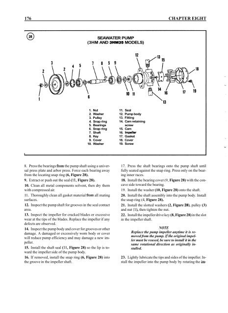
SEAWATER PUMP<br />
(3HM AND 3HM35 MODELS)<br />
1. Nut<br />
2. Washer<br />
3. Pulley<br />
4. Snap ring<br />
5. Bearings<br />
6. Snap ring<br />
7. Shaft<br />
8. Key<br />
9. Cover<br />
10. Washer<br />
11. Seal<br />
12. Pump body<br />
13. Fitting<br />
14. Cam retaining<br />
screw<br />
15. Cam<br />
16. Impeller<br />
17. Gasket<br />
18. Cover<br />
19. Screw<br />
8. Press the bearings from the pump shaft using a universal<br />
press plate and arbor press. Force each bearing away<br />
from the locating snap ring (6, Figure 28).<br />
9. Extract or push out the seal (1 1, Figure 28).<br />
10. Clean all metal components solvent, then dry them<br />
with compressed air.<br />
11. Thoroughly clean all gasket material from all mating<br />
surfaces.<br />
12. Inspect the pump shaft for grooves in the seal contact<br />
area.<br />
13. Inspect the impeller for cracked blades or excessive<br />
wear at the tips of the blades. Replace the impeller if any<br />
defects are observed.<br />
14. Inspect the pump body and cover for grooves or other<br />
damage. A damaged or excessively worn body or cover<br />
will reduce pump efficiency and may damage a new impeller.<br />
15. Install the shaft seal (11, Figure 28) so the lip is toward<br />
the impeller side of the pump body.<br />
16. If removed, install the snap ring (6, Figure 28) into<br />
the groove in the impeller shaft.<br />
17. Press the shaft bearings onto the pump shaft until<br />
fully seated against the snap ring. Press only on the bearing<br />
inner races.<br />
18. Install the bearing cover (9, Figure 28) with the concave<br />
side toward the bearing.<br />
19. Install the washer (10, Figure 28) onto the shaft.<br />
20. Install the shaft assembly into the pump body. Install<br />
the snap ring (4, Figure 28).<br />
21. Install the slotted washers (2, Figure 28), pulley (3)<br />
and nut (I), then tighten the nut.<br />
22. Install the impeller drive key (8, Figure 28) in the slot<br />
in the impeller shaft.<br />
NOTE<br />
Replace the pump impeller anytime it is removed<br />
from the pump. lfthe original impeller<br />
must be reused, be sure to install it in the<br />
same rotational direction as originally installed.<br />
23. Lightly lubricate the tips and sides of the impeller. Install<br />
the impeller into the pump body by rotating the im-


